| Version 29 (modified by , 6 years ago) ( diff ) |
|---|
This wiki page contains tutorials for open-access remotely-accessible full-duplex (FD) radios integrated in the ORBIT and COSMOS testbeds, a collaboration with the Columbia FlexICoN project. The full-duplex transceivers are currently being integrated into COSMOS. All the source code can be found at this GitHub page.
Authors:
- Tingjun Chen, Columbia University: tc2668[at]columbia.edu
- Manav Kohli, Columbia University: mpk2138[at]columbia.edu
Last updated: September 17, 2020
Full-Duplex Wireless in COSMOS
Description
In this tutorial, we will use the two integrated Columbia FlexICoN Gen-2 Wideband FD radios equipped with USRP N210 software defined radios (SDRs) and the Gen-2 frequency-domain equalization (FDE)-based RF canceller box. The testbed may be accessed via ssh. The PC contains several example experiments, which showcase the capabilities of the FD transceivers.
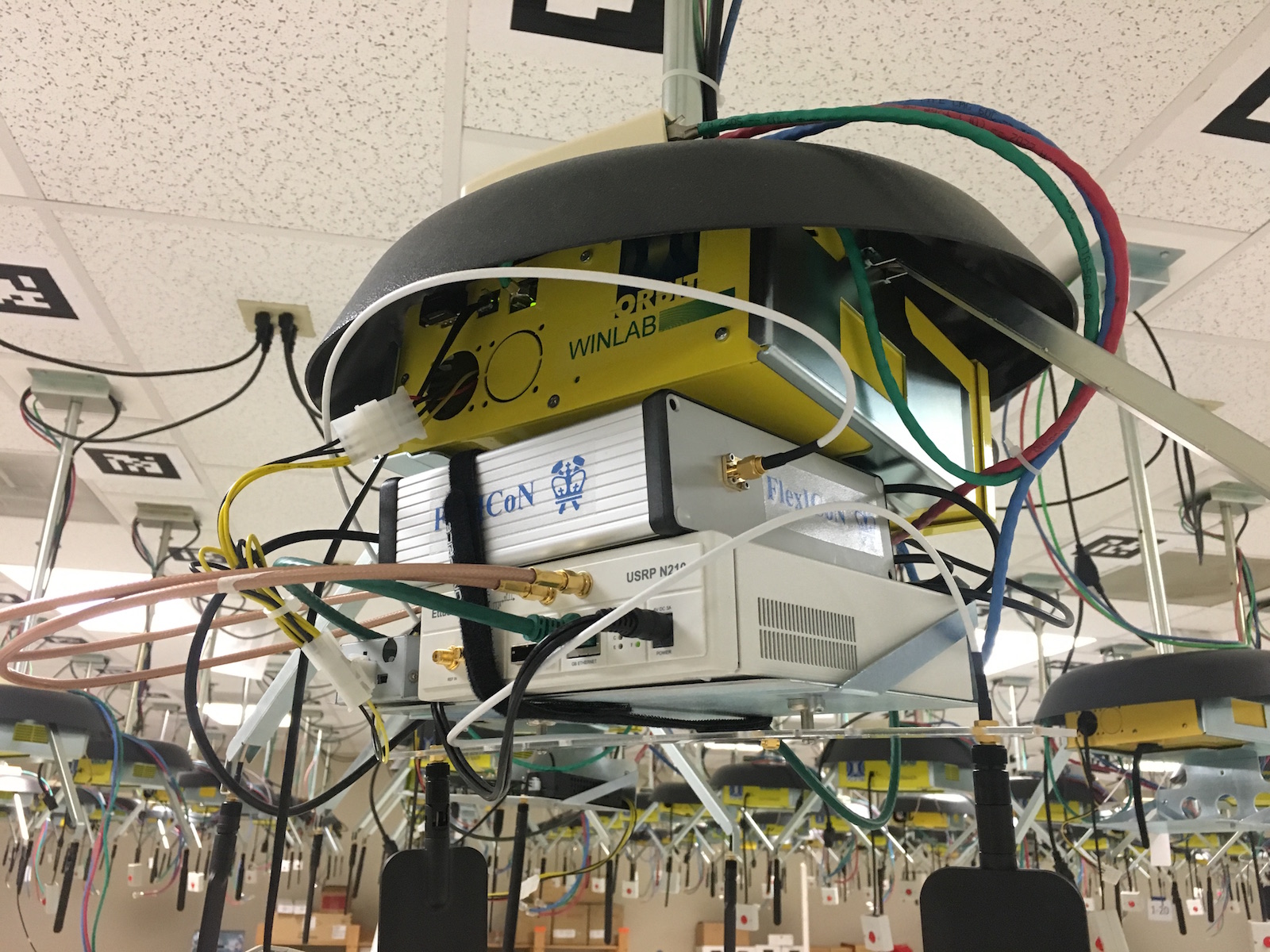
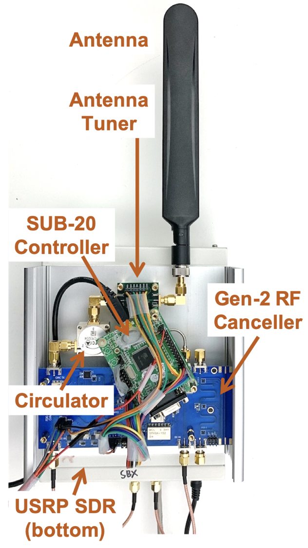
Figure 1: Gen-2 FDE Canceller Boxes in COSMOS Sandbox 2 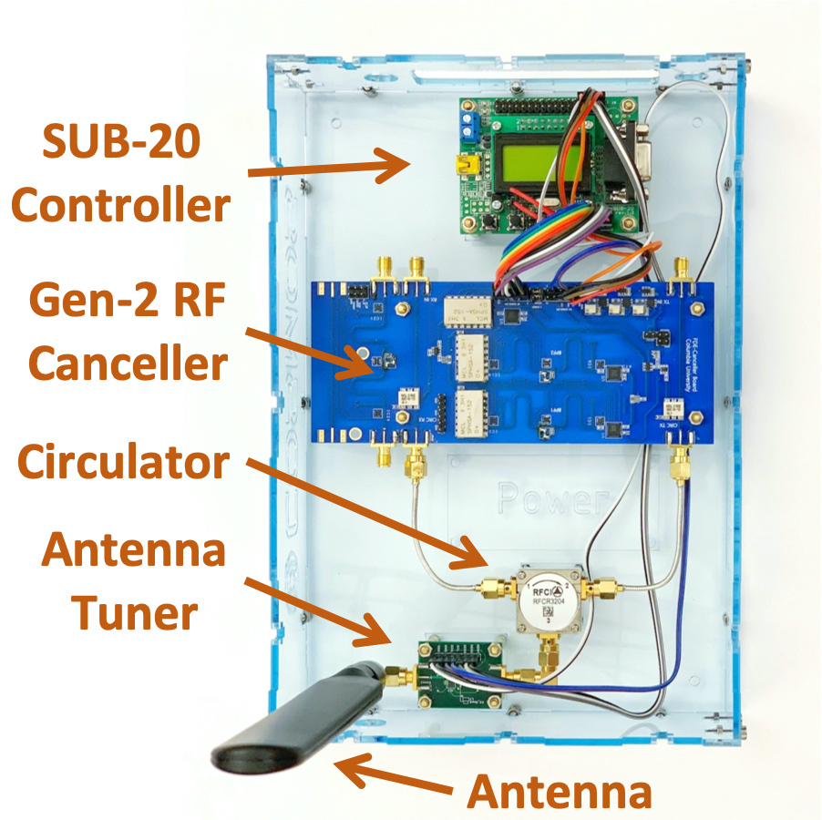

(a) The FlexICoN Gen-2 RF Canceller Box and antenna (b) Rack-mounted, reorganized Gen-2 RF Canceller Box


Publications
For more information about the integration of the FDE-based FD transceivers in COSMOS, please read:
- Manav Kohli, Tingjun Chen, Mahmood Baraani Dastjerdi, Jackson Welles, Ivan Seskar, Harish Krishnaswamy, and Gil Zussman, “Open-access full-duplex wireless in the ORBIT and COSMOS testbeds,” in Proc. ACM MobiCom’20 Workshop on Wireless Network Testbeds, Experimental evaluation & CHaracterization (WiNTECH) (invited), Sept. 2020 (Download) (Demo Abstract)
- Tingjun Chen, Mahmood Baraani Dastjerdi, Jin Zhou, Harish Krishnaswamy, and Gil Zussman, “Wideband Full-Duplex Wireless via Frequency-Domain Equalization: Design and Experimentation,” in Proc. ACM MobiCom'19, Oct. 2019 (Download)
Please cite the above papers if you use the hardware. Please email Tingjun Chen (tc2668[at]columbia.edu) or Manav Kohli (mpk2138[at]columbia.edu) if you use (or plan to use) the full-duplex node or if you have any questions.
Updates
- [08/28/2020] - Details for each available experiment
- [08/23/2020] - General updates
- [02/03/2020] - Updated UHD and GNU Radio versions
- [11/13/2019] - Updated pictures of Gen2 FDE nodes
- [10/20/2019] - Connection to the FDE PC via COSMOS sb2
- [10/07/2019] - Baseline overview of initial COSMOS sandbox status and accessibility
Hardware / Software Resources Utilized
- 2x The Columbia FlexICoN Gen-2 RF Canceller Boxes
- 2x USRP N210
- UHD version 3.14 and GNU Radio 3.7.13.5 are already installed on the PC.
- SUB-20 is a multi-interface USB adapter for providing popular interfaces between PC (USB host) and different hardware devices. Specifically, we use the SUB-20 SPI module to control and configure the Gen-1 RF canceller (see Fig. 1(a)). The user manual can be found here. We are currently working on integration of the SUB-20 control with GNU Radio.
- The
Eigen C++Library is used for basic algebra used in channel estimation and digital self-interference cancellation. The Eigen releases can be found on the this website. We use the latest stable release Eigen 3.3.4 through our testings and experiments. - The source code for the FD example experiments can be found at this GitHub page.
The Gen-2 RF Canceller Box
The Gen-2 RF canceller box is shown in Figure 1(a). It consists of four components:
- Circulator. This provides 15-20dB of isolation between the Tx and Rx.
- Antenna tuner. This allows for better matching to the antenna.
- Gen-2 RF canceller PCB. This is described in further detail below.
- SUB-20 USB to SPI interface. This is used to program the Gen-2 RF canceller PCB over USB.
Figure 2: Gen-2 RF Canceller PCB 

The Gen-2 RF canceller PCB has two paths: the Gen-2 FDE wideband path, and the Gen-1 narrowband path. Further details on the circuit design may be found in [ 2 ], and further details on its use in the Gen-2 RF Canceller box may be found in [ 1 ].
USRP N210 SDR
The Gen-2 RF canceller box is connected to a USRP N210 SDR. This SDR offers good compatibility with our software via UHD and performance up to 25 MHz bandwidth.
COSMOS Sandbox 2
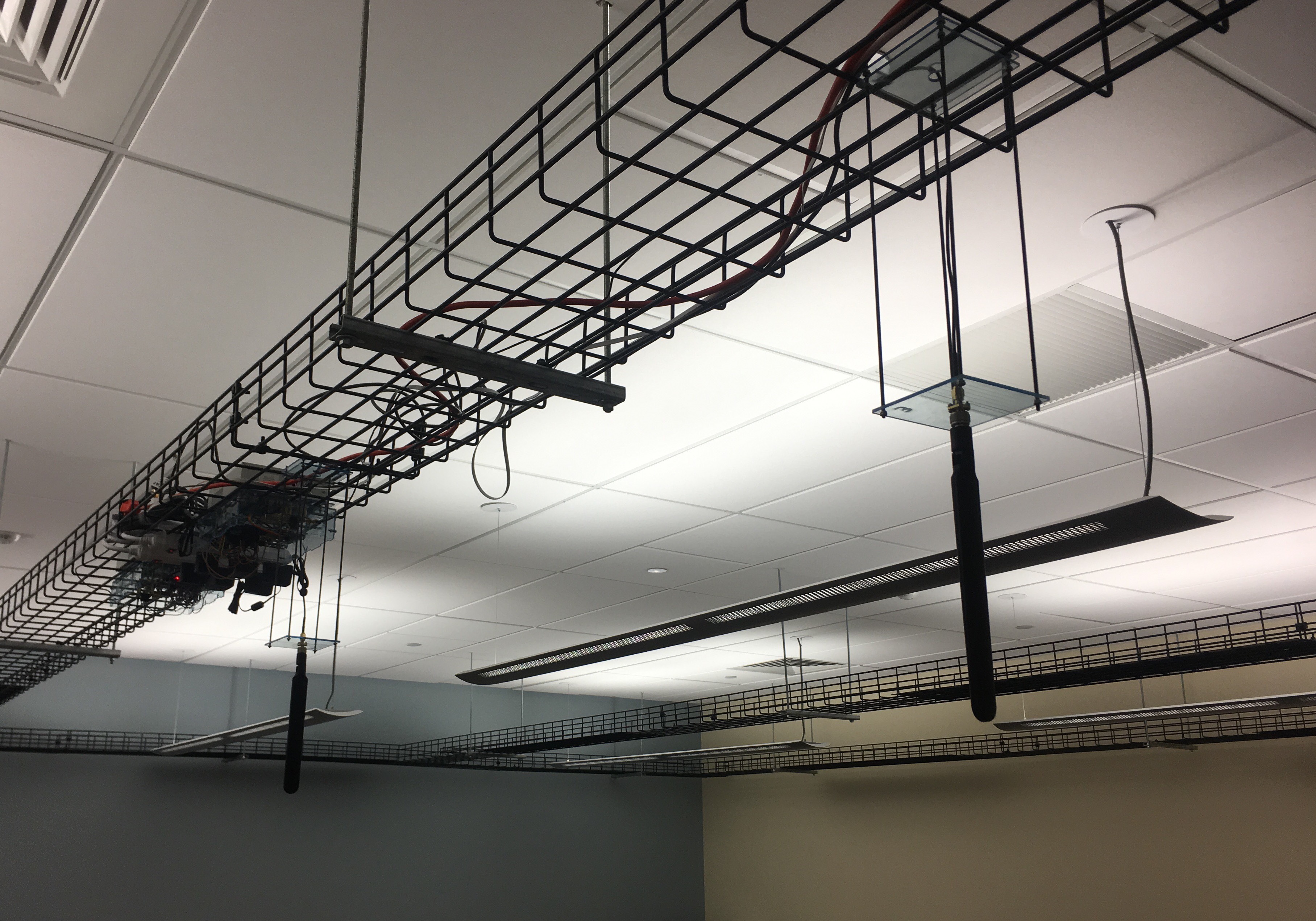
The Gen-2 FDE Canceller Boxes are integrated in COSMOS Sandbox 2 (sb2). The sandbox is located inside a lab at Columbia, allowing for a more controlled environment for the testing and evaluation of experimental hardware, such as the Gen-2 Canceller Boxes. The architecture of Sandbox 2, alongside its integration in the larger COSMOS testbed, is shown in Figure 2 below.
Figure 3: Architecture of COSMOS Sandbox 2 

Tutorial
Set Up
Before you can access the testbed, you need to make a reservation and get it approved. After receiving the reservation's confirmation (approval) email:
- Login into the reserved domain:
ssh -X username@console.sb2.cosmos-lab.org(the-Xoption is for enabling the X11 tunneling). Note: if connecting from macOS, the-Yflag may be needed instead of-X. - Login into the node:
ssh -X sb2@10.109.250.10. The password iscosmossandbox2. After logging in into the node, aFD_Examplesfolder should exist under the home directory which contains some example experiments. Again, see above for using the-Yflag on macOS. - Check the conection and serial number of the USRP2s:
uhd_find_devices. The serial numbers should be316and321.
Running an example experiment
We can open GNU Radio using the following command:
gnuradio-companion &
If X-forwarding is setup correctly for your ssh session, the GNU Radio graphical user interface (GUI) program should open. If X-forwarding is not setup correctly, an error will display saying that the GUI window cannot be opened.
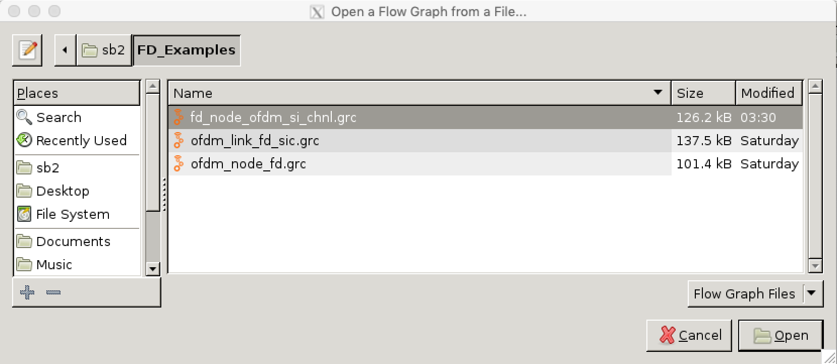
Open an example experiment from the ~/FD_Examples directory. The following experiments are available:
node_level_sic_fd_gui- Demonstrates node-level self-interference cancellation (SIC) and allows the experimenter to configure the RF canceller printed circuitboard (PCB).ofdm_link_fd_gui- Creates an FD link between the two FD radios integrated in COSMOS.prr_fd_gui- Computes the packet reception ratio (PRR) for an FD link.
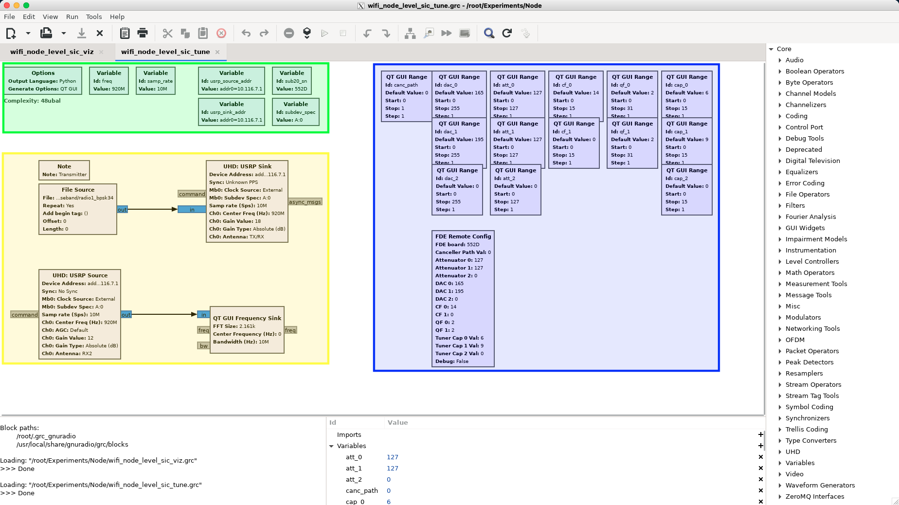
If we open ofdm_link_fd_gui.grc, the following window will show:
Finally, clicking the grey-green play button will run the experiment!
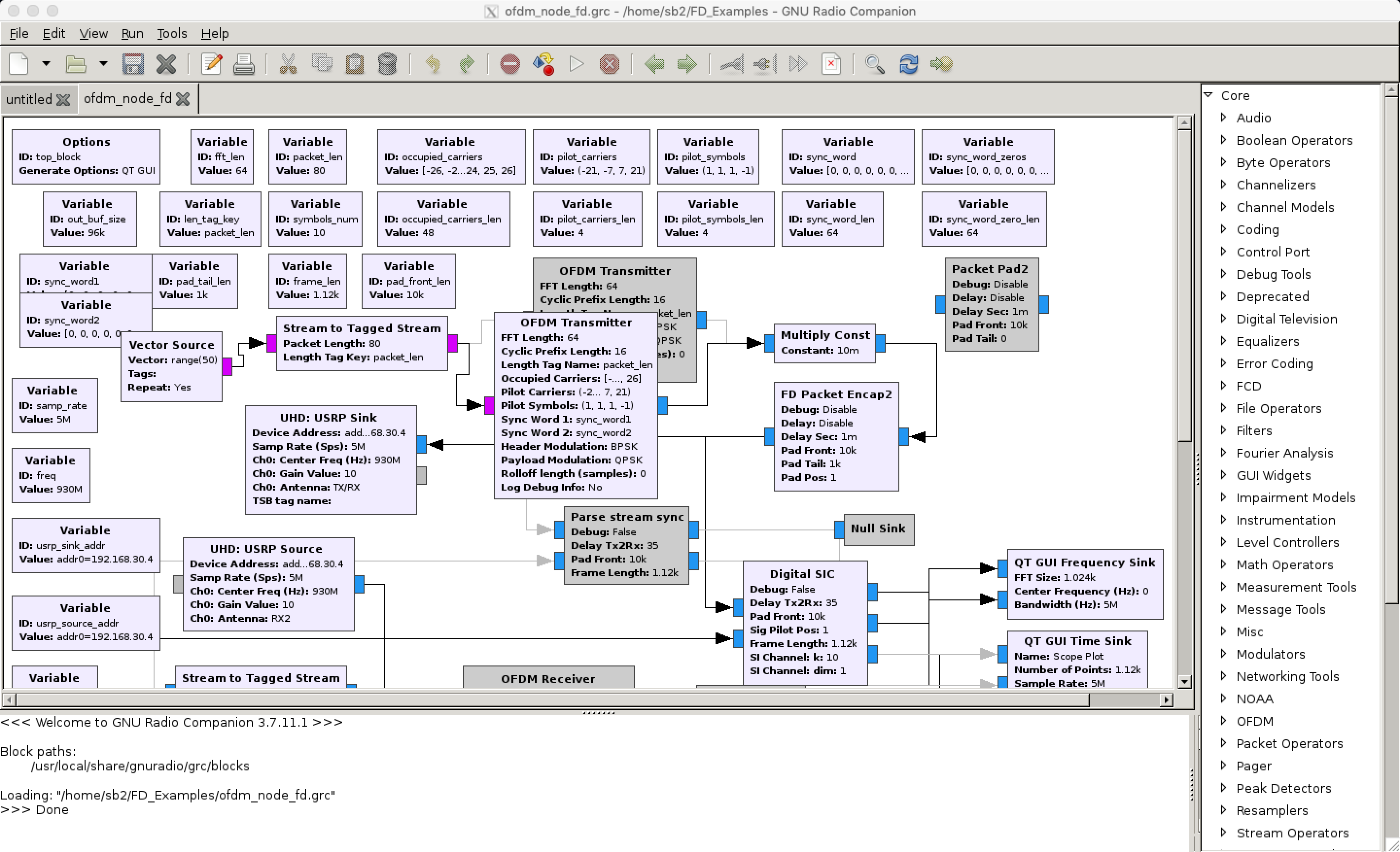
Figure 4: An example FD experiment in the COSMOS testbed 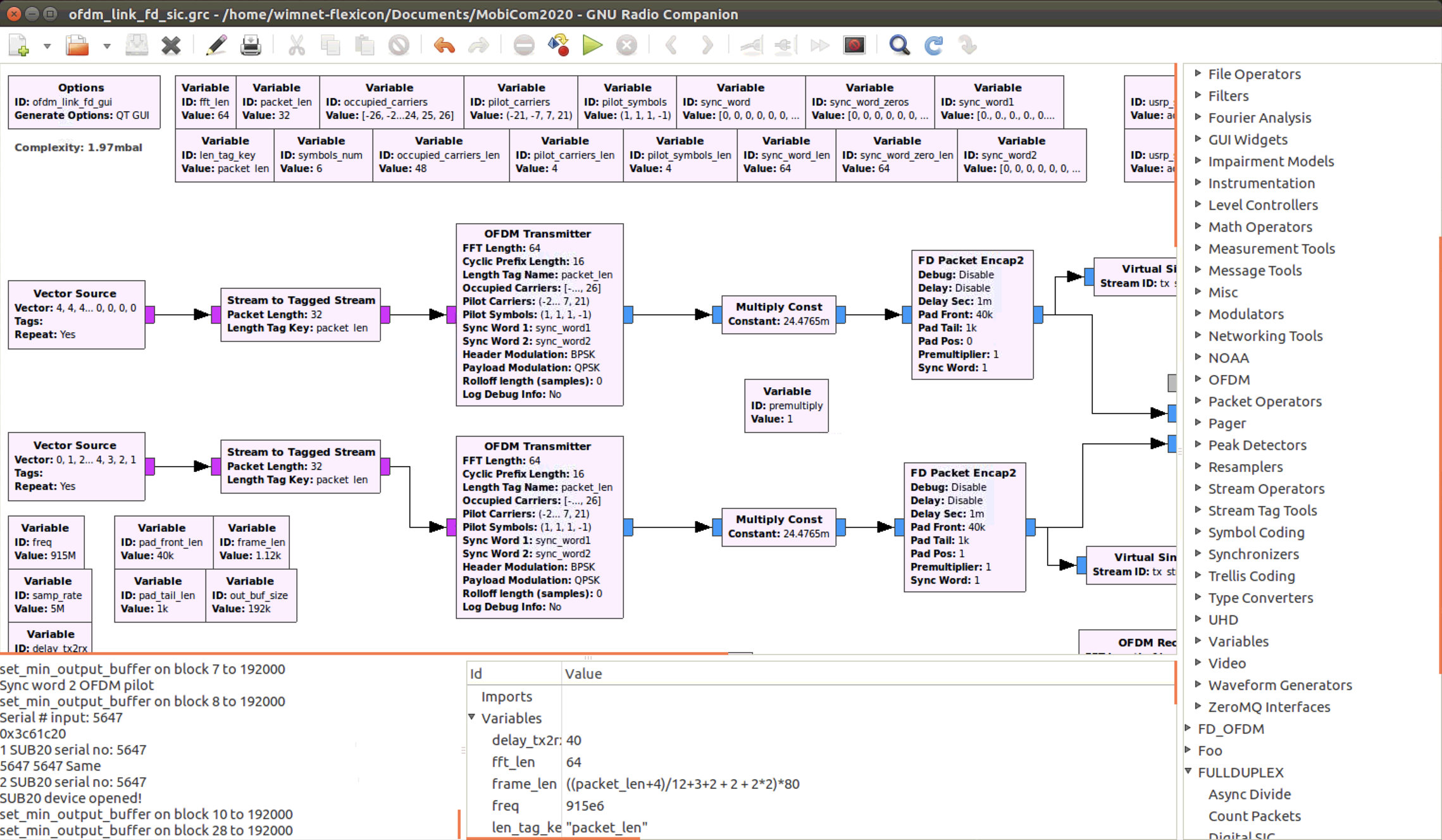
(a) The GNU Radio flowgraph (b) The experiment GUI


Details on the available experiments
In general, the three example experiments provide a means for the experimenter to benchmark the performance of the FD radios, and provide a basis for further experimentation. In this section we provide further detail for each experiment and what they allow the experimenter to observe.
node_level_sic_fd_gui
This experiment's primary use is to visualize the node-level performance of a single FD radio. In this experiment, several performance metrics are visualized:
- The received self-interference (SI) after RF SI cancellation (SIC) and after digital SIC.
- The received power spectra after RF SIC and after digital SIC.
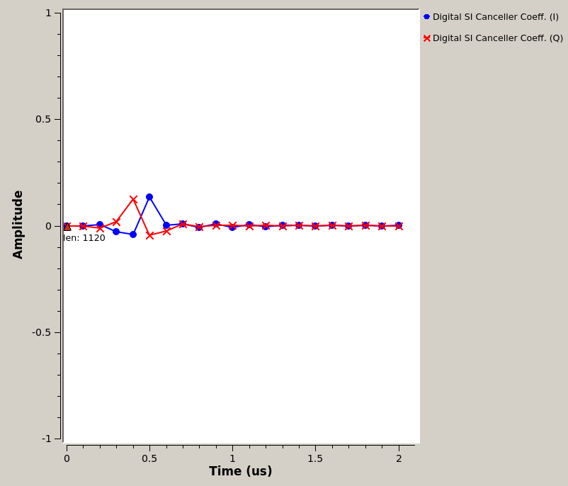
- The complex-valued digital SIC filter taps.
- The estimated SI channel.
Selecting a radio
As there are two radios, this experiment can be run on either one by changing the value of the usrp_sink_addr and usrp_source_addr. The available values are 192.168.30.3 and 192.168.30.4, and usrp_sink_addr and usrp_source_addr must be set to the same value.
Please note that currently, the radio with IP address 192.168.30.4 is temporarily set up with a 10dB attenuator on the Rx in order to equalize link performance between the two radios. Therefore, the received SI will be noticeably smaller for this radio.
Tunable variables
Several other variables can be changed:
freq- the carrier frequency used. The Gen-2 hardware can support roughly 900-1000MHz.samp_rate- the bandwidth used. Ideal choices are 10MHz and 12.5MHz. 20MHz is supported but due to limitations in the USRP receiver chain, 20MHz bandwidth received signals have a bandpass filtered character.tx_gain- this sets the Tx gain in dB. At a setting of 15, the transmit power will be -10dBm. A setting of greater than 22 can degrade performance.
Details on configuring the canceller PCB
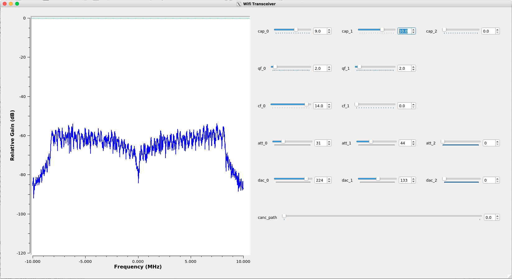
Using the experiment node_level_sic_fd_gui, the experimenter can configure the RF canceller PCB using the experiment GUI. There are 14 sliders:
cap0, cap1, cap2- these control the antenna tuner.att0, att1- The attenuator values for FDE tap 0 and tap 1. Higher values lead to greater attenuation.dac0, dac1- The phase shifter values for FDE tap 0 and tap 1.cf0, cf1- The center frequency for FDE tap 0 and tap 1. Higher values lead to lower center frequency.qf0, qf1- The quality factor for FDE tap 0 and tap 1. Higher values lead to lower quality factor.canc_path- Determines whether the wideband FDE or narrowband Gen-1 canceller path is used. 0 = FDE, 1 = Gen-1.att2- The attenuator values for the Gen-1 path. Higher values lead to greater attenuation.dac2- The phase shifter values for the Gen-1 path.
The experiment GUI will show a visualization of the received power spectrum and self-interference (SI) channel. Using this, the experimenter can generate any desired RF SIC profile.
The GUI also provides a slider for the Tx/Rx delay. This setting is important for digital SIC performance, and the optimal value depends on the bandwidth used. For 10 MHz bandwidth, a delay of 40 should lead to the best digital SIC performance.
Below is the GUI for this experiment, showing the various sliders for the above parameters.
Figure 5: The node-level SIC experiment GUI 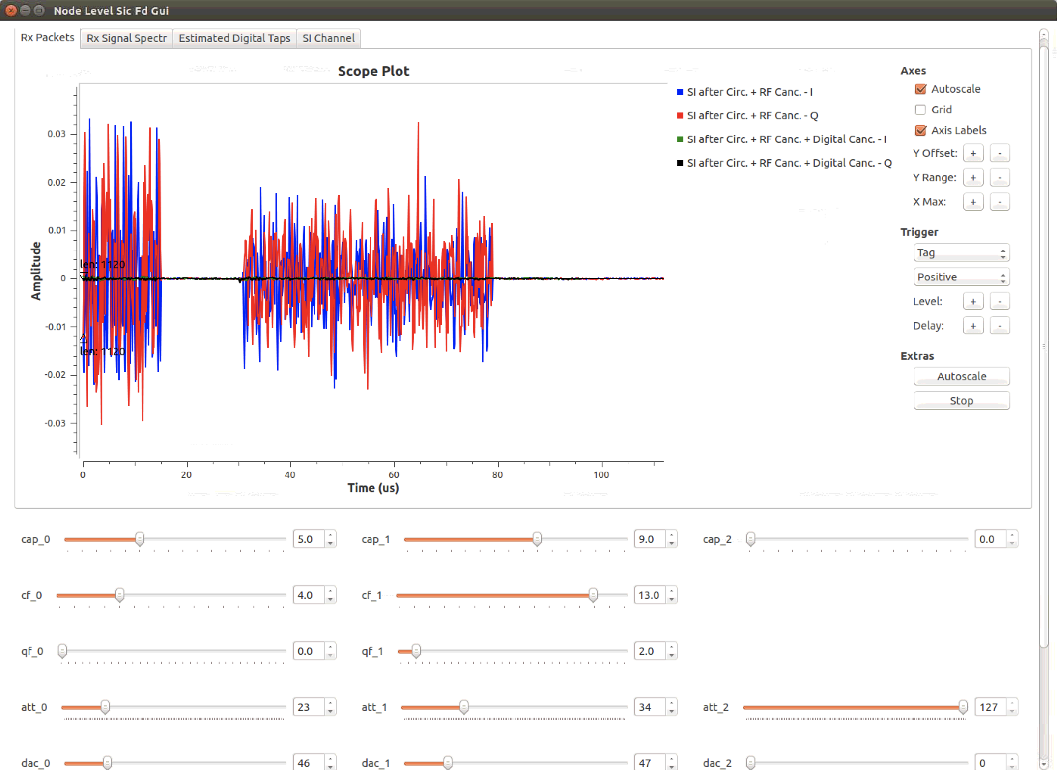

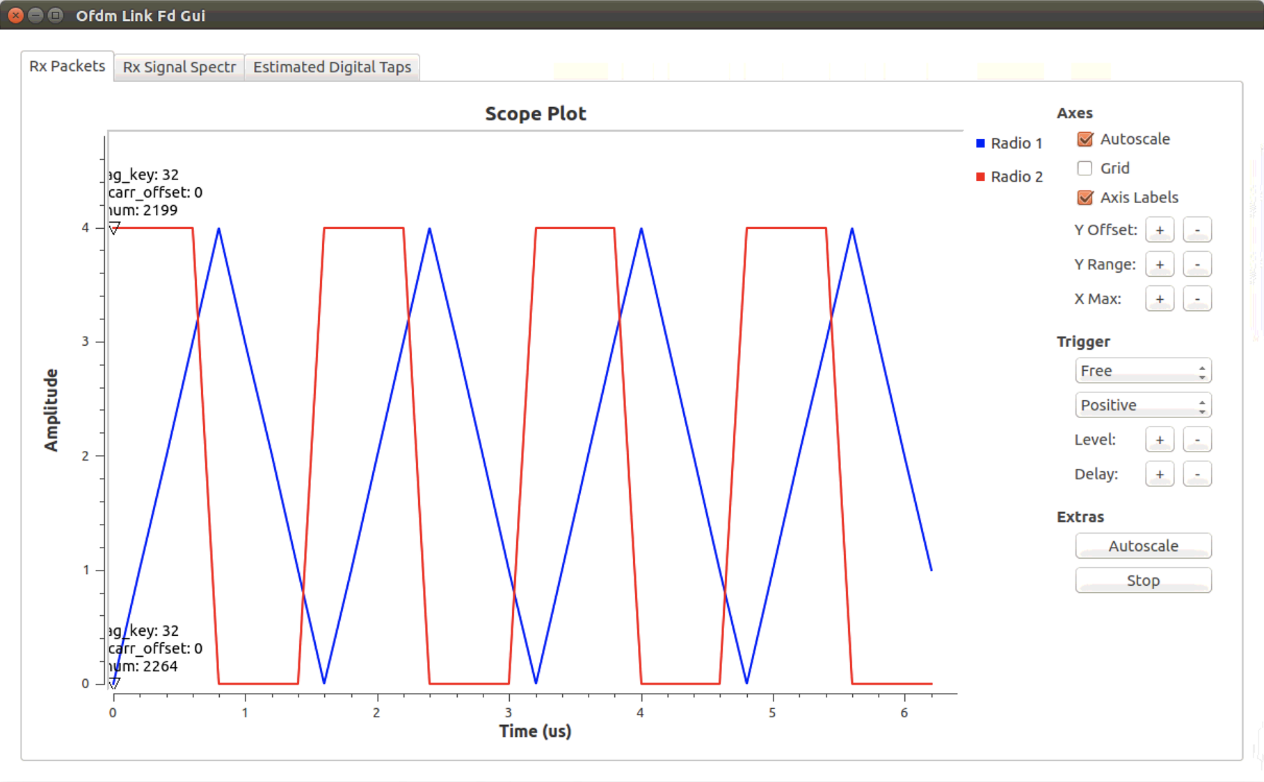
ofdm_link_fd_gui
This experiment makes use of both FD radios to create a FD OFDM link. The radios are synchronized over a MIMO cable, guaranteeing operation in FD mode, where each radio transmits a packet at the same time and successfully decodes the other radio's packet. The following metrics are visualized:
- The packet data values.
- The packet sequence numbers.
- The received signal spectra at each radio after digital SIC.
- The digital SIC filter taps at each radio.
In order for the FD link to operate successfully, each FD radio must be configured to provide sufficient SIC. This can be done with the node_level_sic_fd_gui experiment.
Tunable variables
freq- the carrier frequency used. The Gen-2 hardware can support roughly 900-1000MHz.samp_rate- the bandwidth used. Ideal choices are 10MHz and 12.5MHz. 20MHz is supported but due to limitations in the USRP receiver chain, 20MHz bandwidth received signals have a bandpass filtered character.
The Tx gain is set to allow for successful operation as long as the two radios are achieving adequate SIC. It may be changed if desired through the UHD USRP Sink block on the GNU radio flowgraph.
Below is the GUI for this experiment, showing the packet data values and sequence numbers.
Figure 6: The OFDM link experiment GUI
prr_fd_gui
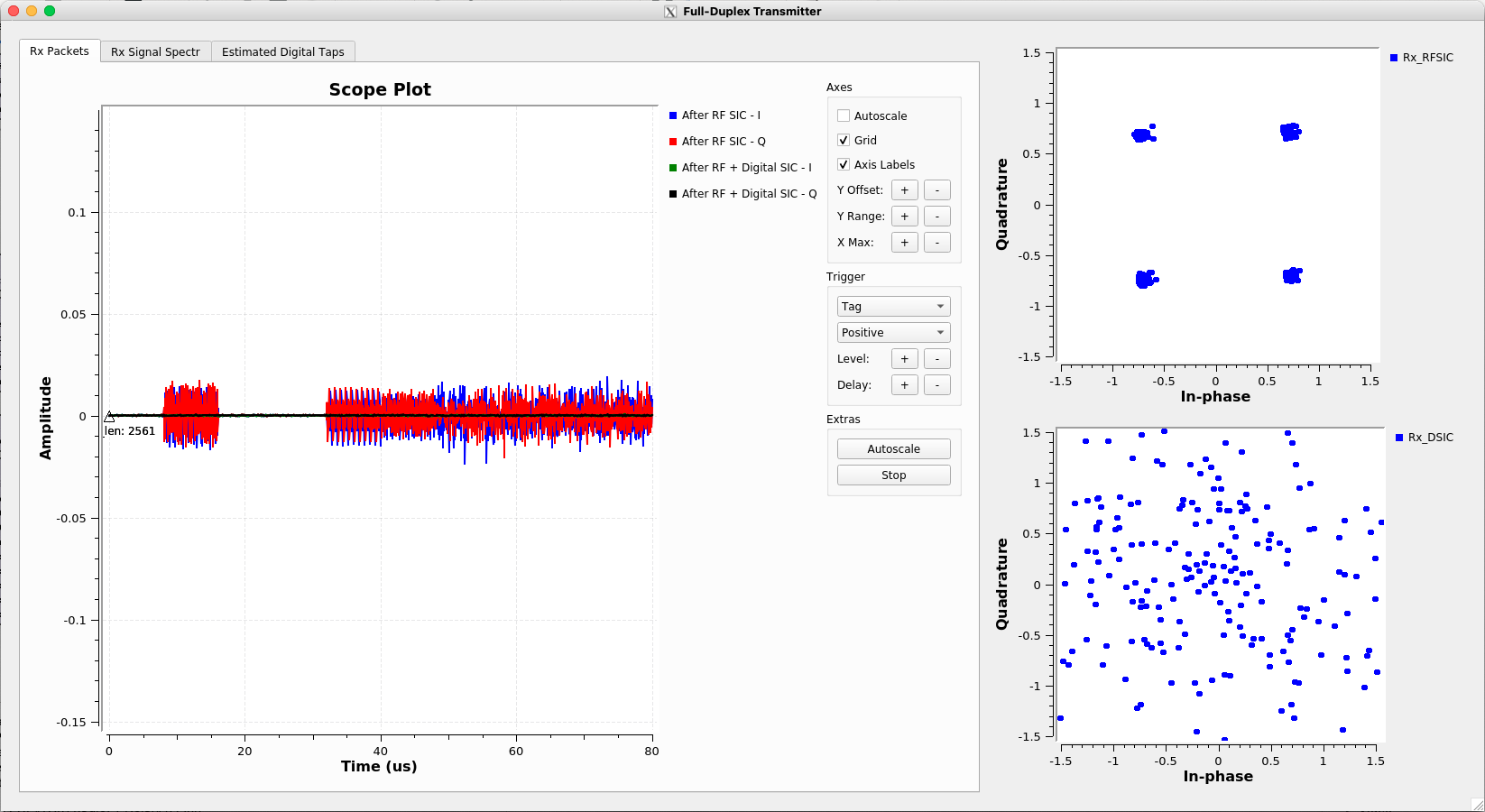
This experiment takes the OFDM link and uses it to compute two metrics: the packet reception ratio (PRR) and signal-to-noise ratio (SNR). These metrics provide a basic link-level benchmark for the FD nodes. In this experiment, the following metrics are visualized:
- The received signal after RF SIC and after digital SIC.
- The measured SNR for each packet.
- The packet reception ratio averaged over the entire experiment run.
- The constellation diagram of the received signal after RF SIC and after digital SIC.
For ease of use, we only display the visualization for a single radio.
As before, in order for the FD link to operate successfully, each FD radio must be configured to provide sufficient SIC. This can be done with the node_level_sic_fd_gui experiment.
Tunable variables
tx_gain- The Tx gain is the key tunable variable as it determines the received packet SNR and therefore the PRR. This can be modified in real time using the GUI, and set prior to the experiment via the QT GUI Range block on the flowgraph.freq- the carrier frequency used. The Gen-2 hardware can support roughly 900-1000MHz.samp_rate- the bandwidth used. Ideal choices are 10MHz and 12.5MHz. 20MHz is supported but due to limitations in the USRP receiver chain, 20MHz bandwidth received signals have a bandpass filtered character.
Below is the GUI for this experiment.
Figure 7: The link PRR experiment GUI 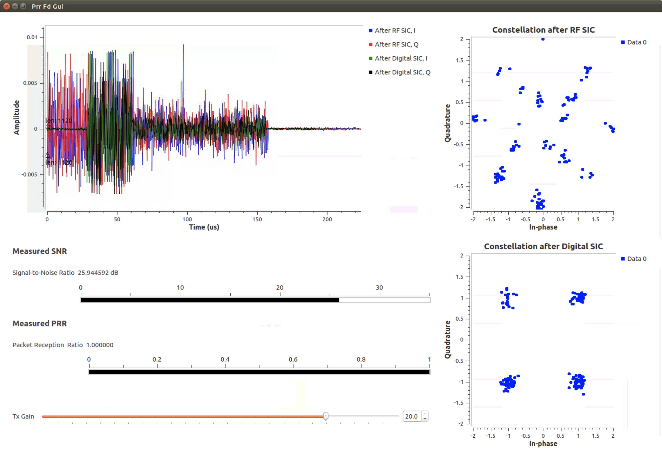

Acknowledgements
This work was supported in part by NSF grants ECCS- 1547406 and CNS-1827923, NSF-BSF grant CNS-1910757, DARPA RF-FPGA and SPAR programs, and a Facebook Fellowship. We thank Jelena Diakonikolas, Guy Farkash, Jakub Kolodziejski, Prasanthi Maddala, Jonathan Ostrometzky, Michael Sherman, and Jin Zhou for their contributions to various aspects of the project.
Full-Duplex Wireless in ORBIT
Description
In this tutorial, we'll use node11-10 in the main grid (equipped with a USRP N210) to transmit and receive a single tone over the air to demonstrate full-duplex wireless capability using the Columbia FlexICoN's Gen-1 Narrowband Frequency-Flat Amplitude- and Phase-based RF Canceller. Pictures of the FlexICoN RF canceller and node11-10 in the main grid equipped with full-duplex capability are below:
Figure 1: The ORBIT-FlexICoN Full-Duplex Node 

(a) The FlexICoN RF Canceller Box (b) Full-Duplex SDR at node11-10 in the ORBIT grid


Publications
For more information, please read:
Manav Kohli, Tingjun Chen, Mahmood Baraani Dastjerdi, Jackson Welles, Ivan Seskar, Harish Krishnaswamy, and Gil Zussman, “Open-access full-duplex wireless in the ORBIT and COSMOS testbeds,” in Proc. ACM MobiCom’20 Workshop on Wireless Network Testbeds, Experimental evaluation & CHaracterization (WiNTECH) (invited), Sept. 2020 (Download) (Demo Abstract)
Please cite the above arXiv report if you use the hardware. Please email Tingjun Chen (tingjun [at] ee.columbia.edu) or Manav Kohli (mpk2138 [at] columbia.edu) if you use (or plan to use) the full-duplex node or if you have any questions.
Updates
- [09/17/2020]: New full-duplex SDR image
flexicon-orbit-v4.ndzreleased. The real-time OFDM-based full-duplex flowgraph and GNU OOT modules have been updated. Obsolete experiments have been removed. - [04/30/2019]: New full-duplex SDR image
flexicon-orbit-v3.ndzreleased. Main new feature includes the implementation of a real-time OFDM-based full-duplex node. - [01/31/2019]: Developed real-time digital SIC as a GNU Radio OOT module.
- [04/05/2018]: New full-duplex SDR image
flexicon-orbit-v2.ndzreleased. New features include (1) GNU Radio OOT module that controls the SUB-20 controller, and (2) integrated full-duplex PSK examples. - [02/28/2018]: PSK examples based on GNU Radio is now available. For more details, please refer to the INFOCOM'18 Demo Abstract.
- [01/08/2018]: The baseline full-duplex SDR image
flexicon-orbit-v1.ndzreleased. This node image includes an UHD benchmark full-duplex transciever example. For more details, please refer to the arXiv report.
Hardware / Software Resources Utilized
- The Columbia FlexICoN Gen-1 RF Canceller, which is a frequency-flat narrowband amplitude- and phase-based RF canceller implemented using discrete components on a PCB. The Gen-1 RF canceller is optimized to have a center operating frequency at 900MHz.
- The source code for the full-duplex transceiver examples, which can be found at this GitHub page. We have also built an ORBIT node image
flexicon-orbit-v4.ndzwith all the required software installed to facilitate the experiments. - USRP N210 with
node11-10in the ORBIT main grid. - SUB-20 is a multi-interface USB adapter for providing popular interfaces between PC (USB host) and different hardware devices. Specifically, we use the SUB-20 SPI module to control and configure the Gen-1 RF canceller (see Fig. 1(a)). The user manual can be found here. We also built a GNU Radio Out-Of-Tree (OOT) module to allow controlling the canceller from within the GNU Radio GUI.
- UHD and GNU Radio are already installed with the imaged SDR node.
- The
Eigen C++Library is used for basic algebra used in channel estimation and digital self-interference cancellation. The Eigen releases can be found on the this website. We used the latest stable release Eigen 3.3.4 through our testings and experiments.
Tutorial
Set Up
Before you can access the testbed, you need to make a reservation and get it approved. After receiving the reservation's confirmation (approval) email:
- Login into reserved domain:
ssh -X username@conslole.grid.orbit-lab.org(the-Xoption is for enabling the X11 tunneing) - Make sure that the full-duplex node is powered down for loading the desired image:
omf tell -a offh -t node11-10 - Load the most updated full-duplex node image (currently
flexicon-orbit-v4.ndz) on the node (this process can take about a few minutes so please be patient):omf load -i flexicon-orbit-v4.ndz -t node11-10 - Turn on the node:
omf tell -a on -t node11-10 - Login into the node:
ssh -X root@node11-10. After login into the node, aflexicon_orbitfolder should exist under the home directory ofnode11-10:~/which contains the source code of this example. You can also retrieve the most recently updated code from the GitHub repository. - Configure the USRP Ethernet interface:
ifconfig eth2 192.168.10.1 netmask 255.255.255.0 up - Run
sudo sysctl -w net.core.rmem_max=50000000andsudo sysctl -w net.core.wmem_max=50000000 - Check the conection and serial number of the USRP N210:
uhd_find_devices. The serial number should beF331D4. - Set an initial configuration for the Gen-1 canceller PCB:
root@node11-10:~ cd flexicon_orbit/fd_transceiver_simple/sub20
root@node11-10:~/flexicon_orbit/fd_transceiver_simple/sub20# ./rf_canc_gen1_config 0 127 16 6 6
Started...
Sub20 device found... Serial Number is 48AB
Device Opened!
...Finished programming DAC with value 0!
...Finished programming ATT with value 127!
...Finished programming CAP1 with value 16!
...Finished programming CAP2 with value 6!
...Finished programming CAP3 with value 6!
Running experiments
We provide two sets of experiments. One set is for GNU Radio, which are identical to the experiments described above in COSMOS and located at ~/flexicon_orbit/experiments/grc/. To run these experiments, open them from GNU radio after running the gnuradio-companion command. Please note that due to there only being one FD radio present in ORBIT, the two link experiments in GNU Radio are not supported. The flowgraphs are kept present for reference.
The other set which are based on UHD, and are legacy experiments - they implement simpler full-duplex transceivers with no available GUI and are also kept for reference.
Details on configuring the canceller PCB
Using the experiment node_level_sic_fd_gui, the experimenter can configure the RF canceller PCB using the experiment GUI. There are 2 sliders:
att_0- The attenuator value for the canceller. Higher values lead to greater attenuation.dac0- The phase shifter values for the canceller.
Available Experiments
node_level_sic_fd_gui (GNU Radio)
The primary use of this experiment is to visualize the performance of the FD radio. As the Gen-1 canceller operates in a narrow band, the cancellation bandwidth will be noticeably less than the Gen-2 FD radios available in COSMOS.
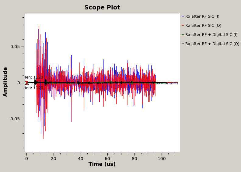
In this experiment, several performance metrics are visualized:
- The received self-interference (SI) after RF SI cancellation (SIC) and after digital SIC.
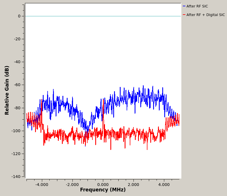
- The received power spectra after RF SIC and after digital SIC.
- The complex-valued digital SIC filter taps.
- The estimated SI channel.
Tunable variables
freq- the carrier frequency used. The Gen-1 hardware can support roughly 900-1000MHz.samp_rate- the bandwidth used. As the canceller is narrowband, we recommend using no more than a 5 MHz bandwidth.
fd_transciever_simple (Terminal + UHD)
This experiment can be used to show the amount of achieved SIC in the RF and digital domains using a command-line interface. It is included here as reference and an example of a full-duplex transceiver implemented in UHD.
We recommend using two terminals here, so one terminal can be used to run the experiment in the foreground while the second is used to control the FD radio.
In Terminal 1
- Prepare the Eigen library (you can skip this step since the image already contains the Eigen library):
cd ~/flexicon_orbit/fd_transceiver_simple/ sudo cp -r Eigen/ /usr/include/ - Build the example (this is already done in the loaded image):
cd ~/flexicon_orbit/fd_transceiver_simple/uhd/
mkdir build
cd build
cmake ../
make
- Run the example with IQ rate
rate, carrier frequencyfreq, TX gaintx-gain, and RX gainrx-gain:The default sine wave has an amplitudecd ~/flexicon_orbit/fd_transceiver_simple/uhd/build/ ./fd_transceiver_simple --tx-args="serial=F331D4" --rx-args="serial=F331D4" --rate 1e6 --freq 900e6 --tx-gain 0 --rx-gain 10
ampl=0.3and wave frequency of 100kHzwave-freq=100e3, which corresponds to a 0dBm TX power level. This terminal window will show the power level at RX baseband, after RF cancellation (before digital) and after digital cancellation, respetively. The UHD program is calibrated with--rx-gain=10, other RX gain values may results in inaccurate power level computation. - An example temrinal output is below:
In this example, since the TX power level is at 0dBm, a total amount of around 90dB self-interference cancellation is achieved, of which 45dB is obtained by the Gen-1 RF canceller, and 50dB is obtained by the digital cancellation.
root@node11-10:~/flexicon_orbit/fd_transceiver_simple/uhd/build# ./fd_transceiver_simple --tx-args="serial=F331D4" --rx-args="serial=F331D4" --rate 1e6 --freq 900e6 --tx-gain 0 --rx-gain 10
linux; GNU C++ version 4.8.4; Boost_105400; UHD_003.010.001.001-0-unknown


Creating the transmit usrp device with: serial=F331D4...
-- Opening a USRP2/N-Series device...
-- Current recv frame size: 1472 bytes
-- Current send frame size: 1472 bytes

.
.
.

Press Ctrl + C to stop streaming...

TX Stream time was: 0 full secs, 0.100064 frac secs

RX Signal Power: -44.093768 dBm (N_FFt = 2048)
RX Res Signal Power: -98.570747 dBm (N_fft = 1024)
Amount of Digital SIC: 54.476979 dB

RX Signal Power: -44.232740 dBm (N_FFt = 2048)
RX Res Signal Power: -98.113147 dBm (N_fft = 1024)
Amount of Digital SIC: 53.880407 dB

RX Signal Power: -43.959299 dBm (N_FFt = 2048)
RX Res Signal Power: -93.406544 dBm (N_fft = 1024)
Amount of Digital SIC: 49.447245 dB

RX Signal Power: -44.179891 dBm (N_FFt = 2048)
RX Res Signal Power: -101.593147 dBm (N_fft = 1024)
Amount of Digital SIC: 57.413256 dB
In Terminal 2 (SUB-20)
- Build the RF canceller configuration code (this is already done in the loaded image):
cd ~/flexicon_orbit/fd_transceiver_simple/sub20/ make - Check the connection to the SUB-20 device using command
lbusb. You should see a XDIMAX devices connected to the USB hub. - Program and configure the RF canceller with the desired values:
In particular, the
cd ~/flexicon_orbit/fd_transceiver_simple/sub20/ ./rf_canc_gen1_config PS-CODE ATT-CODE C1-CODE C2-CODE C3-CODEPS-CODE=0,1,2,...,255andATT-CODE=0,1,2,...,127codes are for configuring the 8-bit phase shifter and the 7-bit attenuator of the Gen-1 RF canceller, respectively. It is recommended to useC1-CODE=16, C2-CODE=6, C3-CODE=6, which provides 20dB isolation from the antenna-circulator interface. You can play with the values ofATTandPSuntil you see good cancellation profile (e.g., low residual self-interference power level) in Terminal 1. - An example terminal output is below:
root@node11-10:~/flexicon_orbit/fd_transceiver_simple/sub20# ./rf_canc_gen1_config 110 30 16 6 6
Started...
Sub20 device found... Serial Number is 48AB
Device Opened!
...Finished programming DAC with value 110!
...Finished programming ATT with value 30!
...Finished programming CAP1 with value 16!
...Finished programming CAP2 with value 6!
...Finished programming CAP3 with value 6!
A Secondary Transmitter Using Node13-8
Once the full-duplex node11-10 is up and running, you can turn on another SDR to transmit to the full-duplex node. Below, we use node13-8 as an example in the 3rd terminal window (Terminal 3).
- Load image, power on, and login into node13-8:
omf tell -a offh -t node13-8
omf load -i baseline-sdr.ndz -t node13-8
omf tell -a on -t node13-8
ssh root@node13-8
- Configure the USRP Ethernet interface:
ifconfig eth2 192.168.10.1 netmask 255.255.255.0 up - Set up a secondary transmitter sending a sine wave at a different frequency (e.g., 200 kHz) than that of the full-duplex node:
Now by analyzing the RX baseband data at node11-10, you will observe the received tone at 200kHz while the self-interence tone at 100kHz is cancelled to the USRP noise floor, which is around -90dBm.
./tx_waveforms --args="serial=F331D4" --rate 1e6 --freq 900e6 gain 10 --wave-type SINE --wave-freq 200e3
The secondary transmitter can also be used while running the GNU radio flowgraph node_level_sic_fd_gui which will visualize the received signal from node13-8.
Acknowledgements
This work was supported in part by NSF grant ECCS-1547406, DARPA RF-FPGA program, DARPA SPAR program, a Qualcomm Innovation Fellowship, a National Instruments Academic Research Grant, Texas Instruments, and Intel. We thank Steven Alfano, Jelena Diakonikolas, Aishwarya Rajen, Jinhui Song, Mingyan Yu for their contributions to various aspects of the project. We thank Ivan Seskar, Jakub Kolodziejski, and Prasanthi Maddala from WINLAB, Rutgers University, for their help on the integration with the ORBIT testbed. We also thank Kira Theuer and Kendall Ruiz from NI and the NI technical support team for their help.
Attachments (22)
- FlexICoN-gen1-node11-10.jpg (614.4 KB ) - added by 7 years ago.
- FlexICoN-gen1-canceller.jpg (476.4 KB ) - added by 7 years ago.
- FlexICoN-gen1-canceller-label.png (1.2 MB ) - added by 7 years ago.
- flexicon_orbit_grc_ofdm_node.png (142.2 KB ) - added by 7 years ago.
- flexicon_orbit_grc_ofdm_node_tab0.png (103.1 KB ) - added by 7 years ago.
- flexicon_orbit_grc_ofdm_node_tab1.png (37.6 KB ) - added by 7 years ago.
- flexicon_orbit_grc_ofdm_node_tab2.png (35.1 KB ) - added by 7 years ago.
- FDExperimentSelection.png (90.2 KB ) - added by 7 years ago.
- GNURadioFDExperiment.png (469.6 KB ) - added by 7 years ago.
-
Gen2Architecture.png
(848.6 KB
) - added by 7 years ago.
Architecture of Gen 2 canceller box
-
Gen2Nodes.jpg
(1.6 MB
) - added by 7 years ago.
Rack-mounted Gen2 FDE nodes
- Gen2Architecture.jpg (872.0 KB ) - added by 6 years ago.
-
Gen2Ceiling.jpg
(1.3 MB
) - added by 6 years ago.
Gen 2 node mounted on rack
- ofdm_link_fd_gui.png (338.7 KB ) - added by 6 years ago.
- GNURadioFDExperiment.2.png (1.1 MB ) - added by 6 years ago.
- node_level_sic_gui.png (582.5 KB ) - added by 6 years ago.
- prr_fd_gui.png (887.5 KB ) - added by 6 years ago.
- Gen2PCB.png (1.7 MB ) - added by 6 years ago.
-
SandboxArchitecture.png
(675.1 KB
) - added by 3 years ago.
Sandbox 2 Architecture
- wifi_node_level_sic_tune_flowgraph.png (252.4 KB ) - added by 3 years ago.
- wifi_node_level_sic_tune_gui.png (77.8 KB ) - added by 3 years ago.
- wifi_node_level_sic_viz_gui.png (133.4 KB ) - added by 3 years ago.