| Version 9 (modified by , 5 years ago) ( diff ) |
|---|
IBM 28GHz PAAM Basics
Description
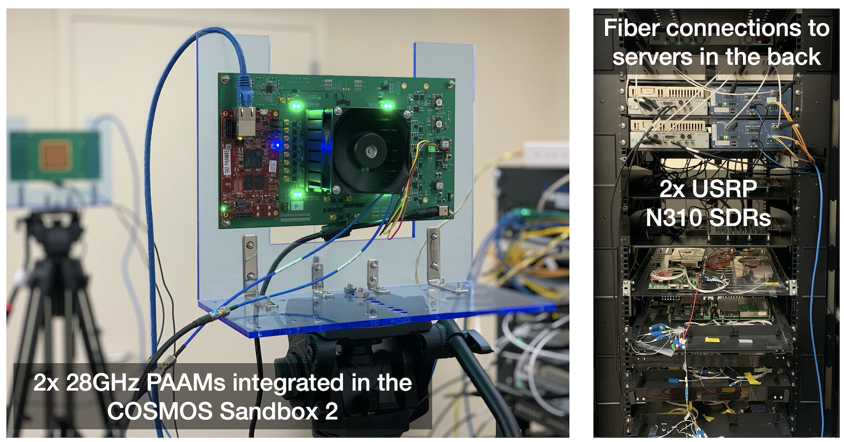
In this tutorial, we demonstrate the basic use of the IBM 28GHz phased array antenna modules (PAAMs) with USRP N310 software-defined radios (SDRs) in the COSMOS Sandbox2 (sb2).
Author: Tingjun Chen, Duke University / Columbia University (tingjun.chen [at] duke [dot] edu)
Last updated: Apr. 11, 2021
Prerequisites
In order to access sb2, create a reservation in sb2 and have it approved by the reservation service. Access to the resources is granted after the reservation is confirmed. Please follow the process shown on the COSMOS getting started page to get started.
Resources Required
- 2 USRP N310 SDRs (
sdr1-s1-lg1andsdr1-md1) - 2 IBM 28GHz PAAMs (
rfdev2-1andrfdev2-2) - 1 Server (
srv1-lg1)
Tutorial Setup
Follow the steps below to gain access to the sb2 console and set up nodes with appropriate images.
- If you don't have one already, sign up for a COSMOS account
- Create a resource reservation on COSMOS sb2
- Login into sb2 console (
console.sb2.cosmos-lab.org) with two SSH sessions. - Make sure all the nodes and devices used in the experiment are turned off:
omf tell -a offh -t sdr1-s1-lg1,sdr1-md1,rfdev2-1,rfdev2-2,srv1-lg1
- Use the
baseline-28ghz-paam.ndznode image with Ubuntu 18.04, UHD 3.15, gnuradio 3.8, and the IBM 28GHz PAAM API. Loadbaseline-28ghz-paam.ndzon the server.omf load -i baseline-28ghz-paam.ndz -t srv1-lg1
- Turn all the required resources on and check the status of all resources
omf tell -a on -t sdr1-s1-lg1,sdr1-md1,rfdev2-1,rfdev2-2,srv1-lg1
omf stat -t system:topo:allres
sshto the the same server from two terminals. In the first terminal, use option -Y for using GUI with gnuradio. In the second terminal, option -Y is not needed as it will be used to control the two IBM 28GHz PAAMs via command lines.[Terminal 1] ssh -Y root@srv1-lg1, [Terminal 2] ssh root@srv1-lg1,
Experiment Execution
Find and prepare USRPs and the IBM 28GHz PAAM API
- The IP addresses for SFP+0 (10G) on
sdr1-s1-lg1andsdr1-md1were hard-coded to10.117.2.1and10.117.3.1, respectively. To access them fromsrv1-lg1, configure the network interfaceeno1as follows:root@srv1-lg1:~# ifconfig eno1 10.117.1.1 netmask 255.255.0.0 mtu 9000 up root@srv1-lg1:~# sudo sysctl -w net.core.wmem_max=62500000 net.core.wmem_max = 62500000 root@srv1-lg1:~# sudo sysctl -w net.core.rmem_max=62500000 net.core.rmem_max = 62500000 root@srv1-lg1:~# ifconfig eno1: flags=4163<UP,BROADCAST,RUNNING,MULTICAST> mtu 9000 inet 10.117.1.1 netmask 255.255.0.0 broadcast 10.117.255.255 inet6 fe80::1e34:daff:fe42:d4c prefixlen 64 scopeid 0x20<link> ether 1c:34:da:42:0d:4c txqueuelen 1000 (Ethernet) RX packets 15305870 bytes 21326136765 (21.3 GB) RX errors 0 dropped 46450 overruns 0 frame 0 TX packets 16288829 bytes 21257264625 (21.2 GB) TX errors 0 dropped 0 overruns 0 carrier 0 collisions 0
- Run
und_find_deviceto make sure that both USRP N310s can be reached:root@srv1-lg1:~# uhd_find_devices [INFO] [UHD] linux; GNU C++ version 7.5.0; Boost_106501; UHD_3.15.0.HEAD-0-gaea0e2de -------------------------------------------------- -- UHD Device 0 -------------------------------------------------- Device Address: serial: 315A35A addr: 10.117.2.1 claimed: True mgmt_addr: 10.116.2.1 mgmt_addr: 10.117.2.1 mgmt_addr: 10.118.2.1 product: n310 type: n3xx -------------------------------------------------- -- UHD Device 2 -------------------------------------------------- Device Address: serial: 3176DF7 addr: 10.117.3.1 claimed: True mgmt_addr: 10.116.3.1 mgmt_addr: 10.117.3.1 mgmt_addr: 10.118.3.1 product: n310 type: n3xx
Execution
Run the experiment
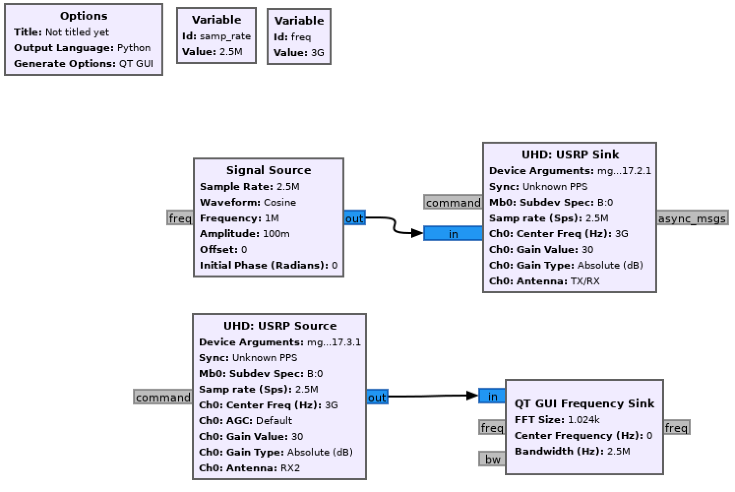
- [Terminal 1] In the first terminal, start gnuradio companion and open the example experiment that established a single tone transmission:
root@srv1-lg1:~# gnuradio-companion example_paam_tone.grc
- [Terminal 1] In gnuradio-companion, start gnuradio-companion, configure the USRP sink (TX) with sdr1-s1-lg1 ("mgmt_addr=10.116.2.1,addr=10.117.2.1") and the USRP source (RX) with sdr1-md1 ("mgmt_addr=10.116.3.1,addr=10.117.3.1"). Set the carrier frequency to 3GHz (3e9) and the subdev to be "B:0" (RF2) on both TX and RX. In this example flowgraph, the sampling rate and the tone frequency are set to be 2.5MHz (2.5e6) and 1MHz (1e6), respectively.

|
- [Terminal 2] In the second terminal, change directory to paam_api/examples/ which contains the example API scripts.
root@srv1-lg1:~# cd paam_api/examples/
- [Terminal 2] First, start PAAM #1 (rfdev2-1) in TX mode with H-polarization using 4 antenna elements on IC 1, and configure the TX beamforming direction to be in the broadside (0,0). Check the current consumption on 2v7_1 and make sure IC1 has been successfully initialized (e.g., 2v7_1 has a current consumption of 1.026A in the example below).
root@srv1-lg1:~/paam_api/examples# python3 setup_betaboard_v1.2.py -c ethernet -a rfdev2-1 --ic 1 -n 4 --txrx tx --pol h --dir 0 0
TRX mode selection: tx
IC(s) used for experiment: [1]
Number of Elements per IC: 4
Polarization: h
Beam direction: (0, 0)
IP address of TX: rfdev2-1
Opened port to FPGA
Logged in to Petalinux
Started command parser on Zynq
sdpar_prog.py /version: Version is PAWR_v1.2.0
Using baseline FPGA control IP
Reset the Phased Array
Initialization of IC 0 was successful
Initialization of IC 1 was successful
Initialization of IC 2 was successful
Initialization of IC 3 was successful
elapsed time for init: 5.458436489105225
Time for PAWR Board utilities configuration: 0.07273483276367188
elapsed time for enable: 0.00990605354309082
elapsed time for steer beam: 0.0026137828826904297
PAAM ID: 0x 2
LO switch: PLL
IF Switches TX_H: 0xF
IF Switches TX_V: 0xF
IF Switches RX_H: 0xF
IF Switches RX_V: 0xF
Index   Name    ADC Volt.   Curr.
0   1v2 21  0.051   0.026
1   1v5 154 0.376   0.753
2   1v8 3   0.007   0.004
3   2v7_0   16  0.039   0.078
4   2v7_1   210 0.513   1.026
5   2v7_2   44  0.108   0.215
6   2v7_3   44  0.108   0.215
7   3v3_pll 367 0.897   0.448
8   5v_uzed 249 0.609   0.609
9   12v 124 0.303   1.010
10  0V  0   0.000   x
11  1V8 735 1.796   x
Closed port to Zynq
Good luck with the experiment!!!
- [Terminal 2] Similarly, start PAAM #2 (rfdev2-2) in RX mode with H-polarization using 4 antenna elements on IC 2, and configure the RX beamforming direction to be in the broadside (0,0). Check the current consumption on 2v7_2 and make sure IC2 has been successfully initialized (e.g., 2v7_2 has a current consumption of 0.821A in the example below).
root@srv1-lg1:~/paam_api/examples# python3 setup_betaboard_v1.2.py -c ethernet -a rfdev2-2 --ic 2 -n 4 --txrx rx --pol h --dir 0 0
TRX mode selection: rx
IC(s) used for experiment: [2]
Number of Elements per IC: 4
Polarization: h
Beam direction: (0, 0)
IP address of TX: rfdev2-2
Opened port to FPGA
Logged in to Petalinux
Started command parser on Zynq
sdpar_prog.py /version: Version is PAWR_v1.2.0
Using baseline FPGA control IP
Reset the Phased Array
Initialization of IC 0 was successful
Initialization of IC 1 was successful
Initialization of IC 2 was successful
Initialization of IC 3 was successful
elapsed time for init: 5.453927516937256
Time for PAWR Board utilities configuration: 0.07044315338134766
elapsed time for enable: 0.008872270584106445
elapsed time for steer beam: 0.002682209014892578
PAAM ID: 0x 4
LO switch: PLL
IF Switches TX_H: 0xF
IF Switches TX_V: 0xF
IF Switches RX_H: 0xF
IF Switches RX_V: 0xF
Index   Name    ADC Volt.   Curr.
0   1v2 127 0.310   0.155
1   1v5 134 0.327   0.655
2   1v8 18  0.044   0.022
3   2v7_0   42  0.103   0.205
4   2v7_1   51  0.125   0.249
5   2v7_2   168 0.411   0.821
6   2v7_3   13  0.032   0.064
7   3v3_pll 34  0.083   0.042
8   5v_uzed 249 0.609   0.609
9   12v 129 0.315   1.051
10  0V  0   0.000   x
11  1V8 735 1.796   x
Closed port to Zynq
Good luck with the experiment!!!
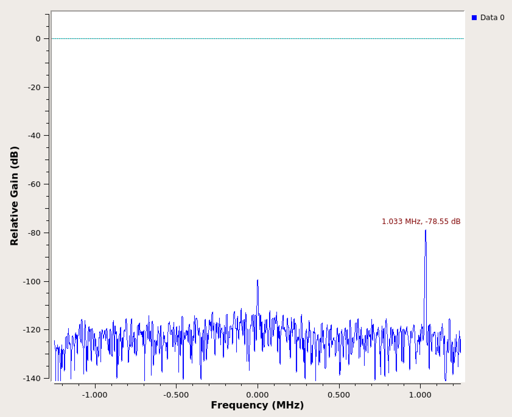
Observe the results
The left figure shows the frequency response of the received tone at 1MHz offset. Experiment can for example increase the link SNR by using more antenna elements (i.e., 8 for TX and 8 for RX) via the PAAM API, and the corresponding results are shown in the right figure.
root@srv1-lg1:~/paam_api/examples# python3 setup_betaboard_v1.2.py -c ethernet -a rfdev2-1 --ic 1 -n 8 --txrx tx --pol h --dir 0 0
root@srv1-lg1:~/paam_api/examples# python3 setup_betaboard_v1.2.py -c ethernet -a rfdev2-2 --ic 2 -n 8 --txrx rx --pol h --dir 0 0
 | 
|
Attachments (4)
-
mmwavePaamBasicsFlowgraph.png
(105.3 KB
) - added by 5 years ago.
mmWave PAAM basics grc flowgraph
- mmwavePaamBasicsFreq_n_4.png (136.6 KB ) - added by 5 years ago.
- mmwavePaamBasicsFreq_n_8.png (138.8 KB ) - added by 5 years ago.
- mmwavePaamBasicsSetup.png (2.8 MB ) - added by 5 years ago.