| Version 16 (modified by , 6 years ago) ( diff ) |
|---|
Site Navigation
- COSMOS Testbed Overview
- Getting Started
- COSMOS/ORBIT User Guide
- COSMOS Portal
- Account Management
- Portal Dashboard
- Directory
- Disk Images
- Community Forum
- Getting Started with the COSMOS Portal
- SSH Access to Testbed Nodes
- Scheduler
- Testbed Status
- Installing Chrome Remote Desktop (CRD) on a Custom Image
- Tutorials
- Architecture
- Resources, Services and APIs
- Datasets
- Hardware Info
- RF Policies & Compliance
Setting an Optical Network on COSMOS Test-bed
This wiki page contains the tutorial of setting up an optical network on the COSMOS Test-bed.
Authors:
Artur Minakhmetov, Telecom Paris : artur.minakhmetov[at]telecom-paris.fr
Craig Gutterman, Columbia University : clg2168[at]columbia.edu
Michael Sherman, Rutgers University : msherman[at]winlab.rutgers.edu
Jiakai Yu, University of Arizona : jiakaiyu[at]email.arizona.edu
Tingjun Chen, Columbia University: tc2668[at]columbia.edu
Change Log
16 October: corrected "tengigabitethernet 1/33/1" to "tengigabitethernet 1/33"
7 October: 2019 (Updated Optical Topology)
Description
Cosmos test-bed provides a possibility to create and use optical networks of various topologies. An example of how an optical network could be configured and used is provided. A simple experiment on switching of optical paths is described.
Compute Nodes and ToR switch interfaces used
- Each compute node has 2 ethernet interfaces:
eo1 from data1 pool
eo2 form data2 pool
- Interfaces from srv1..4.lg1 — data1 pool of interfaces
twentyFiveGigE 1/1/1
twentyFiveGigE 1/1/2
twentyFiveGigE 1/1/3
twentyFiveGigE 1/1/4
- Interfaces from srv1..4.lg1 — data2 pool of interfaces
twentyFiveGigE 1/2/1
twentyFiveGigE 1/2/2
twentyFiveGigE 1/2/3
twentyFiveGigE 1/2/4
- Interfaces from srv1..2.co1 — data1 pool of interfaces
twentyFiveGigE 1/11/3
twentyFiveGigE 1/11/4
- Interfaces from srv1..2.co1 — data2 pool of interfaces
twentyFiveGigE 1/12/3
twentyFiveGigE 1/12/4
Experiment_1 Context

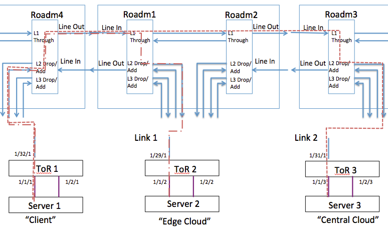
Fig.1 Logical Topology of Experiment_1
Experiment consists in changing the light path from ToR1←→ToR2 to ToR1←→ToR3, representing changing of the light path in C-RAN when “Client” wants to move its base-band processing from “Edge Cloud” to “Central Cloud”.
Experiment includes 3 servers:
srv1-lg1.bed.cosmos-lab.org
srv2-lg1.bed.cosmos-lab.org
srv3-lg1.bed.cosmos-lab.org
Experiment includes 4 ROADMs:
roadm1-co1.cosmos-lab.org (10.104.1.1)
roadm2-co1.cosmos-lab.org (10.104.1.2)
roadm3-co1.cosmos-lab.org (10.104.1.3)
roadm4-co1.cosmos-lab.org (10.104.1.4)
3 interfaces are connected to these servers from data1 pool of ToR interfaces:
twentyFiveGigE 1/1/1 <--> srv1-lg1.bed.cosmos-lab.org
twentyFiveGigE 1/1/2 <--> srv2-lg1.bed.cosmos-lab.org
twentyFiveGigE 1/1/3<--> srv3-lg1.bed.cosmos-lab.org
3 interfaces and 3 transceivers are associated with them in vlans:
vlan 121: twentyFiveGigE 1/1/1 ; tengigabitethernet 1/32/1;
vlan 122: twentyFiveGigE 1/1/2;  tengigabitethernet 1/29/1;
vlan 123: twentyFiveGigE 1/1/2;  tengigabitethernet 1/31/1;
We are assigning next wavelengths to tengigabitethernet:
1553,30 nm 193,00 with bandwidth ~[192.95;193.05] Thz
Setting Up Optical Topology
Setting up an optical topology consists in connecting ROADMs accordingly to the needs of experiment. ROADMs need to be connected correctly to each other and to ToR switch. All interconnections are realized by Calient S320 Switch.

|
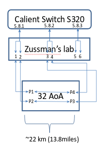
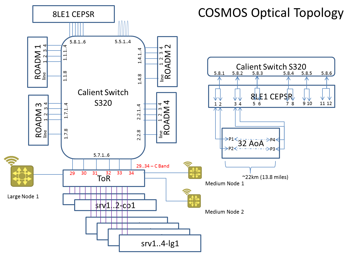
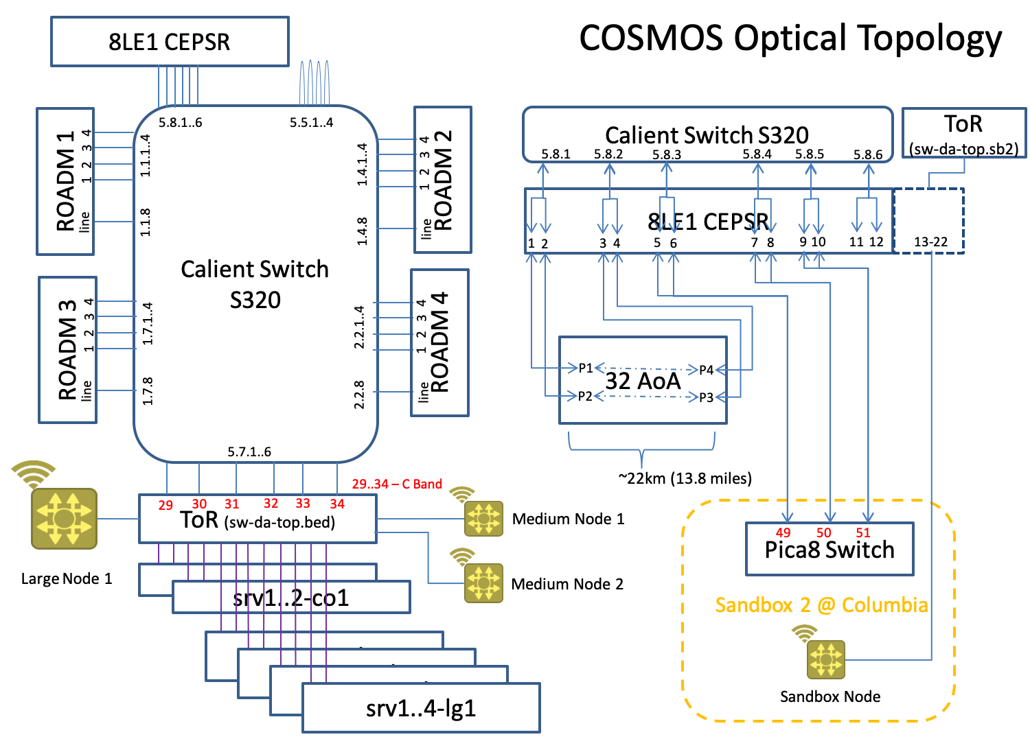
Fig.2 Physical Optical Interconnections.
Calient Switch S320 has ports physically connected to ROADMs, ToR, Prof. Zussman’s lab and 3 loopback connections. All ports are designated in the Fig.2 Physical Optical Interconnections.
In order to support the Experiment_1 logical connections and to realize emulate real distance between Edge Cloud an Central Cloud, one could choose to pass the optical signal through the loop of 22 km passing by 32 Avenue of the Americas, NYC; and organize Client port Connections as Next:
| ID | Ports Connection | Devices Connection | Comment | |||
| 1 | 1.1.1-1.4.1 | ROADM1.port_1 to ROADM2.port_1 | Forming pass through connection between ROADM1 and ROADM2 | |||
| 2 | 1.1.2-5.7.1 | ROADM1.port_2 to ToR.port_29 | Connecting transceiver on ToR on port 29 to ROADM1 add/drop port 2 | |||
| 3 | 1.4.8-5.8.1 | ROADM2.line to 32AoA.P1_P2 | Connecting line port or ROADM2 to port P1_P2 of a 22 km fiber loop going through 32 AoA. | |||
| 4 | 1.7.2-5.7.3 | ROADM3.port_2 to ToR.port_31 | Connecting transceiver on ToR on port 31 to ROADM3 add/drop port 2 | |||
| 5 | 1.7.4-5.5.1 | ROADM3.port_4 to Loopback.port_1 | Connecting ROADM3 add/drop port 4 to a loop-back connection. Is needed to provide “Snake” connection (cf. Setting “Snake” Connection) | |||
| 6 | 2.2.8-1.1.8 | ROADM4.line to ROADM1.line | Connecting line ports of ROADM1 and ROADM4 | |||
| 7 | 5.7.4-2.2.2 | ROADM4.port_2 to ToR.port_32 | Connecting transceiver on ToR on port 32 to ROADM4 add/drop port 2. | |||
| 8 | 5.7.5-2.2.4 | ROADM4.port_4 to ToR.port_33 | Connecting transceiver on ToR on port 33 to ROADM4 add/drop port 4. Is needed to provide “Snake” connection (cf. Setting “Snake” Connection) | |||
| 9 | 5.8.2-1.7.8 | ROADM3.port_2 to 32AoA.P3_P4 | Connection line port or ROADM3 to port P3_P4 of a 22 km fiber loop going through 32 AoA. | |||
Table 1. Calient S320 Connections Table.
ROADMs Configuration
All of these configurations can be performed by Python scripts developed to work with the COSMOS test-bed. The Python commands send NETCONF commands to the ROADM.
Setting “Snake” Connection
Correct ROADM operation requires Line In port of a ROADM to always receive a light. That is why there is a dedicated transceiver (tengigabitethernet 1/33 on ToR) that sends light through all ROADMs by passing through loop-back connection on Calient S320 (port 5.5.1) and redirecting back, so the light is received on the same transceiver. This kind of connection is called “Snake”.
In order maintain this “Snake” for “Experiment_1” next connections form Table 1 must be in place: 1,3,5,6,8,9.
tengigabitethernet 1/33/1 on ToR configuration
Snake Interface (to passe through all ROADMs in loop): 60 (DWDM Channel C60) 1529,55 nm 196,00 Thz with frequency range [195.95,196.05] Thz
MUX/DEMUX configuration
- ROADM 4:
DEMUX IN/OUT port: 5101/5204 MUX IN/OUT port: 4104/4201
- ROADM 1:
DEMUX IN/OUT port: 5101/5201 MUX IN/OUT port: 4101/4201
- ROADM 2:
DEMUX IN/OUT port: 5101/5201 MUX IN/OUT port: 4101/4201
- ROADM 3:
DEMUX IN/OUT port: 5101/5204 MUX IN/OUT port: 4104/4201
ALS Disable Sequence (for 60 seconds)
- ROADM 4 booster,
- ROADM 2 booster,
- ROADM 3 booster,
- ROADM 1 booster,
Setting “Experiment_1” Connections
Configuring ToR1↔ToR2 Connection 1
- ROADM 4:
- Enable MUX port 4102 “From ToR 1”
- Add Connection “Exp1-FromTor1” with Input/ Output Port 4102/4201 with bandwidth [192.95;193.05] (python add_connection.py 10.104.1.4 1 10 in-service false 4102 4201 192950 193050 5 Exp1-FromTor1)
- Enable DEMUX port 5202 “Towards ToR 1”
- Add Connection “Exp1-TorwardTor1” with I/O Port 5101/5202 (python add_connection.py 10.104.1.4 2 10 in-service false 5101 5202 192950 193050 5 Exp1-TorwardTor1)
- ROADM 1:
- Enable MUX port 4102 “From ToR 2”
- Add Connection “From ToR 2” with I/O Port 4102/4201 with bandwidth [192.95;193.05]
- Enable DEMUX port 5202 “Towards ToR 2”
- Add Connection “Towards ToR 2” with I/O Port 5101/5202
Configuting ToR1↔ToR3 Connection 2
- ROADM 4 (Same As For Connection 1):
- Enable MUX port 4102 “From ToR 1”
- Add Connection “From ToR 1” with I/O Port 4102/4201 with bandwidth [192.95;193.05]
- Enable DEMUX port 5202 “Towards ToR 1”
- Add Connection “Towards ToR 1” with I/O Port 5101/5202 with bandwidth [192.95;193.05]
- ROADM 1 <Not Same!>:
- Enable MUX port 4101 “Through Port” (enabled for Snake)
- Add Connection “Through In” with I/O Port 4101/4201 with bandwidth [192.95;193.05]
- Enable DEMUX port 5201 “Through Port” (enabled for Snake)
- Add Connection “Through Out” with I/O Port 5101/5201 with bandwidth [192.95;193.05]
- ROADM 2 (Same As For ROADM1):
- Enable MUX port 4101 “Through Port” (enabled for Snake)
- Add Connection “Through In” with I/O Port 4101/4201 with bandwidth [192.95;193.05]
- Enable DEMUX port 5201 “Through Port” (enabled for Snake)
- Add Connection “Through Out” with I/O Port 5101/5201 with bandwidth [192.95;193.05]
- ROADM 3 (Same As For ROADM4):
- Enable MUX port 4102 “From ToR 3”
- Add Connection “From ToR 3” with I/O Port 4102/4201 with bandwidth [192.95;193.05]
- Enable DEMUX port 5202 “Towards ToR 3”
- Add Connection “Towards ToR 3” with I/O Port 5101/5202 with bandwidth [192.95;193.05]
Network Interfaces Configuration for Experiment_1
Setting Up ToR switch with 3 logical ToR switches
- Preparing the interfaces to be set as VLAN switch ports:
sw-tor-lg1#configure
sw-tor-lg1(conf)#interface twentyFiveGigE 1/1/1
sw-tor-lg1(conf-if-tf-1/1/1)#switchport
sw-tor-lg1(conf-if-tf-1/1/1)#no shutdown
sw-tor-lg1(conf-if-tf-1/1/1)#exit
sw-tor-lg1(conf)#interface twentyFiveGigE 1/1/2
sw-tor-lg1(conf-if-tf-1/1/2)#switchport
sw-tor-lg1(conf-if-tf-1/1/2)#no shutdown
sw-tor-lg1(conf-if-tf-1/1/2)#exit
sw-tor-lg1(conf)#interface twentyFiveGigE 1/1/3
sw-tor-lg1(conf-if-tf-1/1/3)#switchport
sw-tor-lg1(conf-if-tf-1/1/3)#no shutdown
sw-tor-lg1(conf-if-tf-1/1/3)#exit
sw-tor-lg1(conf)#interface tengigabitethernet 1/31/1
sw-tor-lg1(conf-if-te-1/31/1)#switchport
sw-tor-lg1(conf-if-te-1/31/1)#no shutdown
sw-tor-lg1(conf-if-te-1/31/1)#exit
sw-tor-lg1(conf)#interface tengigabitethernet 1/29/1
sw-tor-lg1(conf-if-te-1/29/1)#switchport
sw-tor-lg1(conf-if-te-1/29/1)#no shutdown
sw-tor-lg1(conf-if-te-1/29/1)#exit
sw-tor-lg1(conf)#interface tengigabitethernet 1/32/1
sw-tor-lg1(conf-if-te-1/32/1)#switchport
sw-tor-lg1(conf-if-te-1/32/1)#no shutdown
sw-tor-lg1(conf-if-te-1/32/1)#exit
- Assigning interfaces to VLANs
sw-tor-lg1#configure
sw-tor-lg1(conf)#interface vlan 121
sw-tor-lg1(conf-if-vl-121)#untagged twentyFiveGigE 1/1/1
sw-tor-lg1(conf-if-vl-121)#untagged tengigabitethernet 1/32/1
sw-tor-lg1(conf-if-vl-121)#exit
sw-tor-lg1(conf)#interface vlan 122
sw-tor-lg1(conf-if-vl-122)#untagged twentyFiveGigE 1/1/2
sw-tor-lg1(conf-if-vl-122)#untagged tengigabitethernet 1/29/1
sw-tor-lg1(conf-if-vl-122)#exit
sw-tor-lg1(conf)#interface vlan 123
sw-tor-lg1(conf-if-vl-123)#untagged twentyFiveGigE 1/1/3
sw-tor-lg1(conf-if-vl-123)#untagged tengigabitethernet 1/31/1
sw-tor-lg1(conf-if-vl-123)#exit
sw-tor-lg1(conf)#exit
- Assigning a wavelength to transceivers:
sw-tor-lg1#configure
sw-tor-lg1(conf)#interface tengigabitethernet 1/32/1
sw-tor-lg1(conf-if-te-1/32/1)#wavelength 1553.3
sw-tor-lg1(conf-if-te-1/32/1)#exit
sw-tor-lg1(conf)#interface tengigabitethernet 1/29/1
sw-tor-lg1(conf-if-te-1/29/1)#wavelength 1553.3
sw-tor-lg1(conf-if-te-1/29/1)#exit
sw-tor-lg1(conf)#interface tengigabitethernet 1/32/1
sw-tor-lg1(conf-if-te-1/32/1)#wavelength 1553.3
sw-tor-lg1(conf-if-te-1/32/1)#exit
sw-tor-lg1(conf)#exit
- Verify VLANs:
sw-tor-lg1#show vlan

Codes: * - Default VLAN, G - GVRP VLANs, R - Remote Port Mirroring VLANs, P - Primary, C - Community, I - Isolated
       O - Openflow, Vx - Vxlan
Q: U - Untagged, T - Tagged
   x - Dot1x untagged, X - Dot1x tagged
   o - OpenFlow untagged, O - OpenFlow tagged
   G - GVRP tagged, M - Vlan-stack
   i - Internal untagged, I - Internal tagged, v - VLT untagged, V - VLT tagged

    NUM    Status    Description                     Q Ports
    121    Active                                    U Te 1/32/1
                                                     U Tf 1/1/1
    122    Active                                    U Te 1/29/1
                                                     U Tf 1/1/2
    123    Active                                    U Te 1/31/1
                                                     U Tf 1/1/3
Configuring Compute Nodes (Servers srv1..3-lg1)
- Install net-tools:
sudo apt install net-tools
- Configure interfaces eo1 and assign IP addresses:
native@srv1-lg1:~$ sudo ifconfig eno1 192.168.1.1 netmask 255.255.255.0
native@srv2-lg1:~$ sudo ifconfig eno1 192.168.1.2 netmask 255.255.255.0
native@srv3-lg1:~$ sudo ifconfig eno1 192.168.1.3 netmask 255.255.255.0
Perform Experiment_1
- Establish Connection ToR1↔ToR2.
- Try Ping from Srv1 to Srv2:
native@srv1-lg1:~$ ping 192.168.1.3
PING 192.168.1.3 (192.168.1.3) 56(84) bytes of data.
64 bytes from 192.168.1.3: icmp_seq=1 ttl=64 time=0.460 ms
64 bytes from 192.168.1.3: icmp_seq=2 ttl=64 time=0.423 ms
- Establish Connection ToR1↔ToR2.
- Try Ping from Srv1 to Srv3.
Attachments (5)
- Experiment_1.png (83.0 KB ) - added by 7 years ago.
- 32_AoA.png (13.6 KB ) - added by 7 years ago.
- COSMOS_Optical.png (94.3 KB ) - added by 7 years ago.
- COSMOS_Optical_v1.png (94.4 KB ) - added by 7 years ago.
- COSMOS optical topology_V7.png (203.1 KB ) - added by 7 years ago.
Download all attachments as: .zip