Site Navigation
- COSMOS Testbed Overview
- Getting Started
- COSMOS/ORBIT User Guide
- COSMOS Portal
- Account Management
- Portal Dashboard
- Directory
- Disk Images
- Community Forum
- Getting Started with the COSMOS Portal
- SSH Access to Testbed Nodes
- Scheduler
- Testbed Status
- Installing Chrome Remote Desktop (CRD) on a Custom Image
- Tutorials
- Architecture
- Resources, Services and APIs
- Datasets
- Hardware Info
- RF Policies & Compliance
Networks
There exist three primary networks that are accessible by experimenters in COSMOS. Device connections to these networks are determined by the number of interfaces and their maximum bandwidth. Every device has at least a connection to the Control Plane. Then depending on the number of additional interfaces, the device may have a connection to either one or both of the Data Planes. Please see the device specific pages for more detailed information on Data Plane connectivity.
Control Plane
The control plane is a physically separate network designed to facilitate infrastructure control and user access to end devices. The control plane network runs on top of Dell S4048-ON switches providing up to 10G connectivity between devices. Please note that performance on the control plane is not guaranteed or deterministic and the network is only meant for experiment coordination and debugging.
Data Plane
There exist two parallel data plane networks that are available to experimenters. The data plane networks are interconnected with Dell Z9100-ON switches providing up to 100G connectivity between devices. The switches are built on the Broadcom Tomahawk chipset and support Openflow 1.3 as well as ONIE. The data planes are meant for latency and bandwidth sensitive experiment traffic where performance is intended to be deterministic.
Instrumentation Plane
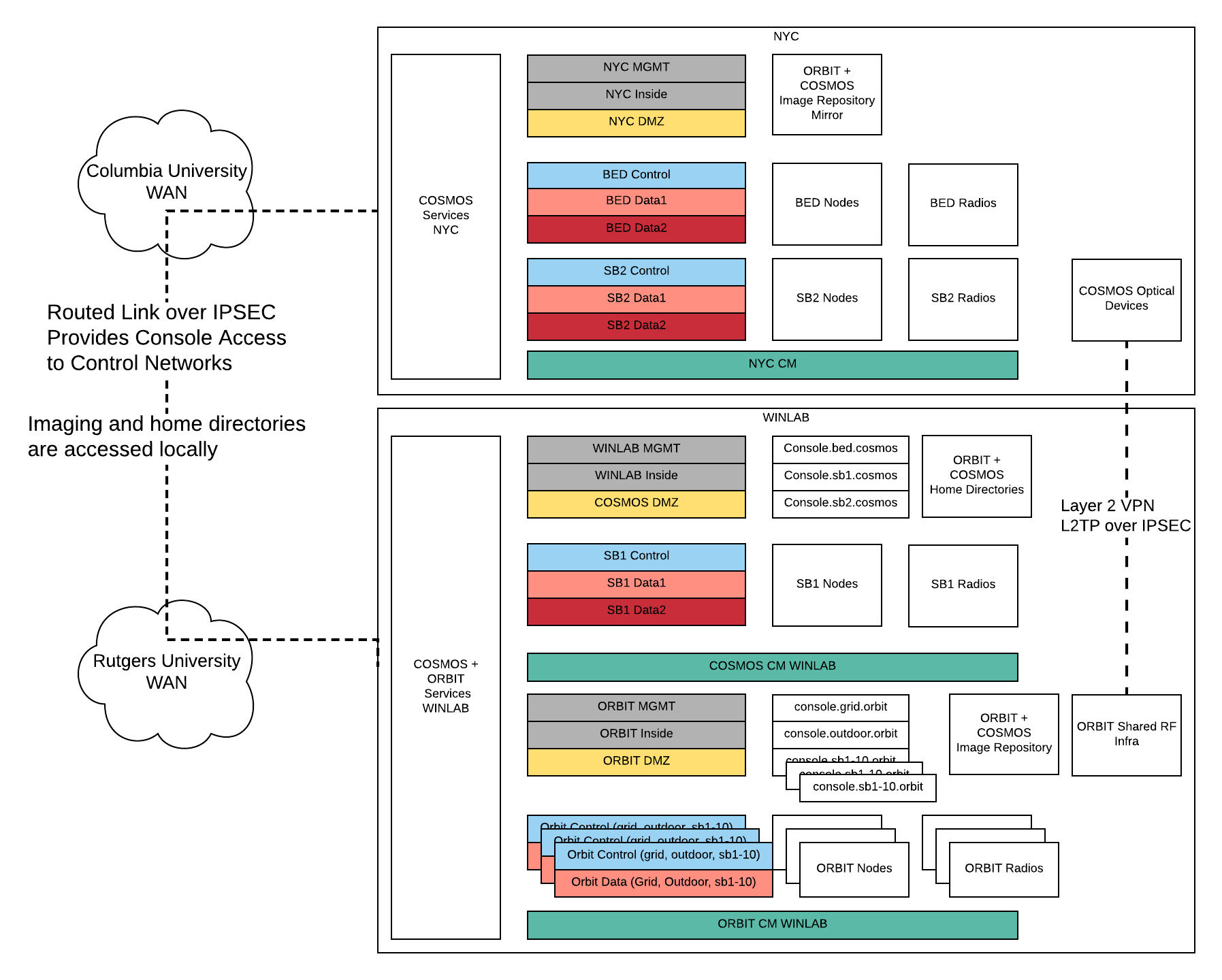
The Instrumentation network is special, in that it is accessible to experiments, but is managed by infrastructure services. This provides, for example, optical or RF devices that need direct L2 access to multiple domains. Access to this network is granted on a case by case basis to experiments (i.e. based on device capabilities, domain and/or experimenter experience). This is also the only L2 network that spans sites, via L2 Tunnel.
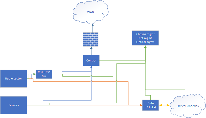
User facing network architecture

All radio devices and servers are connected to the control and data logical networks, described above. The data network is further connected to the optical underlay. By making requests to the appropriate service, users can configure logical connections to use a particular path across both ethernet switches and and the underlying optical fabric. In addition, user can have full control of the switches in the Data Plane.
Non-user facing networks connect services, and manage hardware.
Locality within the network
While all devices within the network may be connected, there are bandwidth and latency considerations. For convenience, devices within the same physical location / topology have matching suffixes. For example, sdr1-s1-lg1 and sdr2-s1-lg1 share the same next hop switches for their data planes, as do srv1-lg1 and srv2-lg1. Explanation of these suffixes is available at naming page.
Isolation and infrastructure
We enforce a split between "Control", "Data", and "Infrastructure" networks. Control and Infrastructure share common physical hardware (Switches, cables, etc.), using VLANs to provide isolation. Together these provide services and user access to the testbed.
The Data networks operate on physically separate hardware, to preserve repeatability of experiments, and to prevent experiments from interfering with testbed services.
L2 Networks do not span sites, with access being done via L3 tunnels, or via public internet.
Consoles give users access from outside and communicate with services on the DMZ network, and access to the testbed devices over control.
Network Roles

Each Domain has a control network, that is statically configured, as well as two configurable data plane networks. Imaging and other configuration tasks is done via the control network, while experiment and radio traffic is passed on the data networks.
In addition, each "site" has some infrastructure networks.
- CM: used for power control of nodes, not directly accessible to users, instead is managed by services
- Inside: Private network for service traffic, VM Storage traffic, etc.
- DMZ: User accessible network for service traffic
- MGMT: Private network for control of network devices, VM Cluster synchronization, etc.
Logical Sites
Currently, there are two logically distinct sites.
- The NYC COSMOS Deployment
- bed.cosmos, including exterior radios and optical underlay
- sb2.cosmos
- WINLAB, 671 Rt 1 South, North Brunswick, NJ
- sb1.cosmos
VLAN Assignment
| VLAN ID | Subnet | Name | Location |
|---|---|---|---|
| 37 | 10.37.0.0/16 | sb1 Control | WINLAB |
| 38 | 10.38.0.0/16 | sb1 Data1 | WINLAB |
| 39 | 10.39.0.0/16 | sb1 Data2 | WINLAB |
| 110 | 10.110.0.0/16 | bed Control | NYC |
| 111 | 10.111.0.0/16 | bed Data1 | NYC |
| 112 | 10.112.0.0/16 | bed Data2 | NYC |
| 116 | 10.116.0.0/16 | sb2 Control | NYC |
| 117 | 10.117.0.0/16 | sb2 Data1 | NYC |
| 118 | 10.118.0.0/16 | sb2 Data2 | NYC |
Attachments (2)
- COSMOS Net Arch.png (77.9 KB ) - added by 7 years ago.
- cosmos_logical_net.png (19.9 KB ) - added by 7 years ago.
Download all attachments as: .zip