| Version 26 (modified by , 4 years ago) ( diff ) |
|---|
Site Navigation
- COSMOS Testbed Overview
- Getting Started
- COSMOS/ORBIT User Guide
- COSMOS Portal
- Account Management
- Portal Dashboard
- Directory
- Disk Images
- Community Forum
- Getting Started with the COSMOS Portal
- SSH Access to Testbed Nodes
- Scheduler
- Testbed Status
- Installing Chrome Remote Desktop (CRD) on a Custom Image
- Tutorials
- Architecture
- Resources, Services and APIs
- Datasets
- Hardware Info
- RF Policies & Compliance
Setting up COSMOS' Optical Network topology using the Mininet-Optical Software Emulator
This wiki page is intended for participants attending COSMOS workshop in SIGCOMM 2022. This contains a tutorial for setting up a virtual/simulated optical network using Mininet-Optical. Mininet-Optical was developed as part of the COSMOS and COSM-IC projects and adds optical network emulation and simulation capabilities to Mininet to support software emulation of optical and packet-optical networks, including modeling of optical transmission effects and impairments.
This is a Mininet-Optical version of the tutorial at Workshops/Sig Comm2022/Optical Tutorial and is intended to show how an experiment designed for COSMOS' optical network testbed (hardware) may be adapted for use in a software emulation environment running on Linux (for example in a VM on a laptop or other hardware server), and how Mininet-Optical may be used to design experiments that will later be run on the COSMOS hardware testbed.
The Mininet-Optical version of this tutorial implements the same network topology and the same experiment as the hardware testbed tutorial, but there are differences between the software and hardware environments.
Authors:
Agastya Raj, Trinity College Dublin: rajag[at]tcd.ie
Julie Raulin, Tyndall National Institute: julie.raulin[at]tyndall.ie
Bob Lantz, Columbia University: rlantz[at]cs.stanford.edu
This software tutorial is based on the hardware tutorial by Zehao Wang and Tingjun Chen (and a previous hardware tutorial by Chen et al..) Please refer to Workshops/Sig Comm2022/Optical Tutorial for comparison with the hardware environment.
Description
The COSMOS testbed enables creation and use of optical networks of various topologies. Similarly, Mininet-Optical enables creation of virtual optical networks using software emulation. An example of how an optical network could be configured and used is provided. A simple experiment on switching of optical paths is described.
Compute Nodes and ToR switch interfaces used
- Each compute node has 1 Ethernet interface:
srv1_co1-eth0
srv1_lg1-eth0
srv2_lg1-eth0
- There are three ToR Ethernet interfaces:
sw-da-co1-eth1
sw-da-lg1-eth2
sw-da-lg1-eth3
- There are three WDM transceivers, with separate output and input ports:
sw-da-co1-wdm320/321
sw-da-lg1-wdm290/291
sw-da-lg1-wdm310/311
- and two COMB Sources, with Line-out ports:
comb1-wdm4201
comb2-wdm4201
Network Context

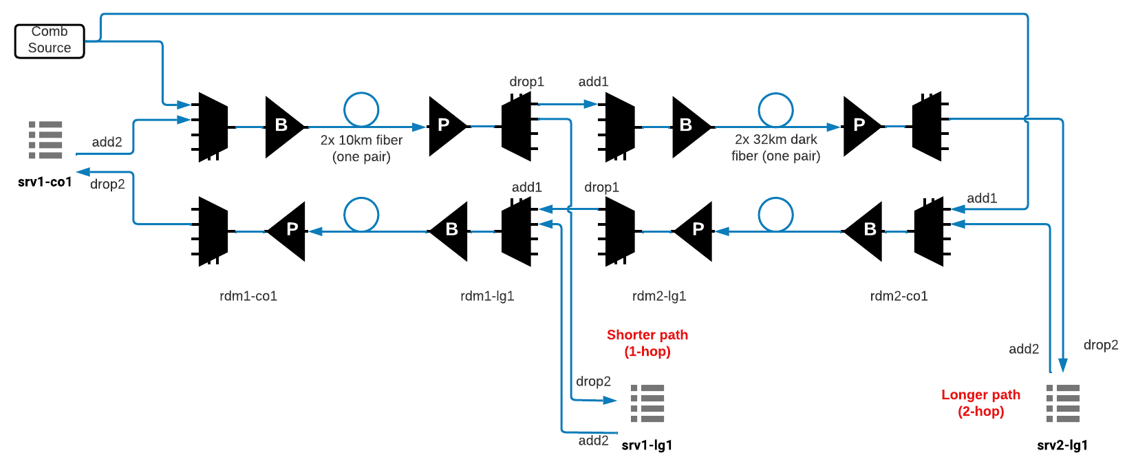
Fig.1 Logical Topology of the hardware used
This experiment demonstrates optical switching between the short (1-hop) path, between srv1_co1 and srv1_lg1, and the long (2-hop) path, between srv1_co1 and srv2_lg1. It represents changing of the light path in C-RAN when a "Client" wants to dynamically change its base-band processing location between a nearby "Edge Cloud" and a further away "Central Cloud".
To simulate the topology in hardware, the network component names are kept the same.
Experiment includes 3 servers:
srv1_co1 (192.168.1.1/24)
srv1_lg1 (192.168.1.2/24)
srv2_lg1 (192.168.1.3/24)]
Experiment includes 4 ROADMs:
rdm1-co1 (localhost:1834)
rdm1-lg1 (localhost:1832)
rdm2-lg1 (localhost:1833)
rdm2-co1 (localhost:1844)
2 ToR Switches are connected to the 3 servers on the following interfaces:
sw-da-co1-eth1 <--> srv1_co1-eth0
sw-da-lg1-eth2 <--> srv1_lg1-eth0
sw-da-lg1-eth3 <--> srv2_lg1-eth0
3 Ethernet interfaces and 3 WDM transceivers will be connected within the ToR switch:
sw-da-co1-eth1 ; sw-da-co1-wdm320/321  (output/input)
sw-da-lg1-eth2 ; sw-da-lg1-wdm290/291  (output/input)
sw-da-lg1-eth3 ; sw-da-lg1-wdm310/311  (output/input)
We are assigning the following wavelength to the transceivers:
1543.60 nm, 194.35 THz with bandwidth ~[194.30;194.40] THz
This corresponds to channel 61 in Mininet-Optical's as well as COSMOS' default channel grid.
We are assigning the following bands of wavelength to the comb sources to simulate background traffic:
Band 1: [1560.50,1564.10] nm ~ [191.80,192.25] THz. This corresponds to channels 10-19 in Mininet-Optical's and COSMOS' default channel grid.
Band 2: [1548.40,1552.00] nm ~ [193.30,193.75] THz. This corresponds to channels 40-49 in Mininet-Optical's and COSMOS' default channel grid.
Band 3: [1532.60,1536.10] nm ~ [195.30,195.75] THz. This corresponds to channels 80-89 in Mininet-Optical's and COSMOS' default channel grid.
Starting Mininet-Optical on COSMOS' node
Before starting this tutorial, you will have already logged in to Ubuntu image on Cosmos node. If you don't have access to the COSMOS' console already, you can follow the sign-up and installation instructions at Workshops/Sig Comm2022/Signup Instructions To save the hassle of installing, we have already installed Mininet-Optical on the node you are using.
To start our tutorial on Mininet-Optical, follow the below steps:
- Log in to the node, and fetch the latest version of Mininet-Optical
root@node# cd mininet-optical
root@node:~/mininet-optical# git fetch
root@node:~/mininet-optical# git checkout cosmos-tutorial
root@node:~/mininet-optical# git pull --rebase
root@node:~/mininet-optical# make install certs
- Run a sample script to check Mininet-Optical has been installed correctly.
root@node:~/mininet-optical# sudo PYTHONPATH=. python3 ./examples/simplelink.py test
Expected output:
*** Creating network
*** Adding controller
*** Adding hosts:
h1 h2
*** Adding switches:
t1 t2
*** Adding links:
 (h1, t1) (h2, t2) (t1, t2)
*** Configuring hosts
h1 h2
*** Starting controller
c0
*** Starting 2 switches
t1 t2 ...

simplelink.py: simple link between two terminals

This is very close to the simplest fully emulated packet-optical
network that we can create.
...
...
*** Ping: testing ping reachability
h1 -> h2
h2 -> h1
*** Results: 0% dropped (2/2 received)
*** Stopping 1 controllers
c0
*** Stopping 3 links
...
*** Stopping 2 switches
t1 t2
*** Stopping 2 hosts
h1 h2
*** Done
If your output looks like above, mininet-optical is successfully working on your computer. Please exit the current Mininet-Optical script, by typing exit or pressing control-D at the mininet-optical> prompt:
If you are facing an error, please make sure you have followed the steps above, or consult one of our organizers for resolution.
The tutorial topology and a sample configuration script should be found in ~/mininet-optical/examples/sigcommtutorial.py and ~/mininet-optical/examples/config-sigcommtutorial.sh.
If you want to test out Mininet-Optical on your computer after the tutorial, we have provided necessary resources in the appendix.
Setting Up the Optical Topology
Starting the Mininet-Optical Network
All of these commands should be run in a terminal window for the VM or server where Mininet-Optical is installed.
- We will run Mininet-Optical from the top directory of the source tree. You should be able to run the tutorial script to create the emulated network by running the following command:
root@node:~/mininet-optical# sudo PYTHONPATH=. examples/sigcommtutorial.py
- This should start up Mininet-Optical, create the tutorial network, and start the CLI:
SIGCOMM22 mini-tutorial topology


comb1 -> rdm1co1 <--10km--> rdm1lg1 || rdm2lg1 <--34km--> rdm2co1 <- comb2
           |                  |                              |
        swda_co1           swda_lg1--------------------------|
           |                  |                              |
        srv1_co1           srv1_lg1                       srv2_lg1

This is for the SIGCOMM22 mini-tutorial at:
https://wiki.cosmos-lab.org/wiki/Workshops/SigComm2022/MininetOptical

*** Starting CLI:
mininet-optical>
Mininet-Optical CLI commands may be entered at the mininet-optical> prompt.
Controller Configuration
Now that we have the topology setup for the network, we want to configure the lightpaths and pass packets using NETCONF, which is network management protocol for software defined networks. We have this configuration in the file examples/config-sigcommtutorial.py, which we require to run from another terminal window.
(Note: if you want to use the X11 features of Mininet, such as the xterm or plot commands, you may need to use sudo HOME=~ rather than just sudo.)
If you don't have one open already, open up another terminal window with the below instructions. For ease of use, we will call this terminal-2 hereafter:
Opening another terminal window in Orbit
- Open another terminal window in your computer/laptop (Linux:CTRL+ALT+T, Mac: CMD+T, Windows: CTRL+Shift+T)
- SSH to Orbit console with your username. This is the same step used to login to Orbit console in hardware tutorial Workshops/Sig Comm2022/Signup Instructions according to your assigned group.
user@local-computer:~$ ssh user@<console-name>
- Connect to the node where Mininet-Optical is installed. This <node> is the same where you are logged in the previous terminal window.
user@console:~$ ssh root@<node>
- Enter source directory
root@<node>:# cd ~/mininet-optical
root@<node>:~/mininet-optical#
Unless specified otherwise, all of the configuration commands below should be entered in terminal-2 at the shell prompt. All of these configurations can be performed by Python scripts developed to work with the COSMOS test-bed. The Python commands send NETCONF commands to the ROADM.
Running the configuration script
Run the script with the following command in terminal-2
root@node:~/mininet-optical# bash -x ./examples/config-sigcommtutorial.sh
This executes the configuration file which establishes the ground connections first and turns on the transceivers.
Mininet-Optical's Terminal is the equivalent of the ToR switch
which contains Ethernet interfaces as well as WDM transceivers. Instead of using a Cisco-style CLI to configure it, we use its
default REST API.
As noted above, 194.35 THz corresponds to channel C61 on Mininet-Optical's default 50GHz channel grid. C1's middle frequency is 191350 GHz, so C61 is at 191350 + 60*50 = 194350 GHz.
We walk through this script below to deep dive into what's happening:
- Connect Ethernet interfaces to Transceivers and set channel
curl "$swda_co1/connect?node=swda-co1ðPort=1&wdmPort=320&wdmInPort=321&channel=61" curl "$swda_lg1/connect?node=swda-lg1ðPort=2&wdmPort=290&wdmInPort=291&channel=61" curl "$swda_lg1/connect?node=swda-lg1ðPort=3&wdmPort=310&wdmInPort=311&channel=61"
- Turn on all transceivers and comb sources
curl "$swda_co1/turn_on?node=swda-co1"
curl "$swda_lg1/turn_on?node=swda-lg1"
curl "$comb1/turn_on?node=comb1"
curl "$comb2/turn_on?node=comb2"
- Configure Ethernet interfaces and assign IP addresses:
...
m=~/mininet/util/m
...
$m srv1_co1 ifconfig srv1_co1-eth0 192.168.1.1/24
$m srv1_lg1 ifconfig srv1_lg1-eth0 192.168.1.2/24
$m srv2_lg1 ifconfig srv2_lg1-eth0 192.168.1.3/24
Note that ~/mininet/util/m can be used to 'log in' to any one of the servers much as you would with ssh (but it actually spawns a shell in the appropriate cgroup/network namespace.)
Performing base test configuration
Once you execute the script, the script will ask for a prompt to perform a base test. This test pings 'srv-co1' to 'srv-lg1'; and pings 'srv-co1' to 'srv2_lg1' without establishing any lightpath connections between ROADMS. Press Return key to perform the base test.
*** Base test before configuration
press return to test base configuration>
...
*** srv1_co1 pinging srv1_lg1
PING 192.168.1.2 (192.168.1.2) 56(84) bytes of data.
From 192.168.1.1 icmp_seq=1 Destination Host Unreachable
From 192.168.1.1 icmp_seq=2 Destination Host Unreachable
From 192.168.1.1 icmp_seq=3 Destination Host Unreachable

--- 192.168.1.2 ping statistics ---
3 packets transmitted, 0 received, +3 errors, 100% packet loss, time 2168ms
...
*** srv1_co1 pinging srv2_lg1
PING 192.168.1.3 (192.168.1.3) 56(84) bytes of data.
From 192.168.1.1 icmp_seq=1 Destination Host Unreachable
From 192.168.1.1 icmp_seq=2 Destination Host Unreachable
From 192.168.1.1 icmp_seq=3 Destination Host Unreachable

--- 192.168.1.3 ping statistics ---
3 packets transmitted, 0 received, +3 errors, 100% packet loss, time 2192ms
As expected, none of the servers are able to ping each other because lightpath connections have not been established as of yet.
Ping Servers Manually
You can also ping all the servers manually in the mininet-optical CLI to check the connections with below steps:
- Go back to terminal-1 to the mininet-optical CLI. Here you can ping one server from another to check the connection between them. Let's try to ping srv1_lg1 from srv1_co1 using the command
srv1_co1 ping -c3 srv1_lg1as shown below:mininet-optical> srv1_co1 ping -c3 srv1_lg1 PING 10.0.0.2 (10.0.0.2) 56(84) bytes of data. From 10.0.0.1 icmp_seq=1 Destination Host Unreachable From 10.0.0.1 icmp_seq=2 Destination Host Unreachable From 10.0.0.1 icmp_seq=3 Destination Host Unreachable --- 10.0.0.2 ping statistics --- 3 packets transmitted, 0 received, +3 errors, 100% packet loss, time 2081ms
- You should also try to ping srv2_lg1 from srv1_co1 using the below command:
mininet-optical> srv1_co1 ping -c3 srv2_lg1
PING 10.0.0.3 (10.0.0.3) 56(84) bytes of data.
From 10.0.0.1 icmp_seq=1 Destination Host Unreachable
From 10.0.0.1 icmp_seq=2 Destination Host Unreachable
From 10.0.0.1 icmp_seq=3 Destination Host Unreachable

--- 10.0.0.3 ping statistics ---
3 packets transmitted, 0 received, +3 errors, 100% packet loss, time 2142ms
As expected, you cannot ping srv1_lg1 and srv2_lg1 from srv1_co1 right now, because no connections have been established.
Configuring ROADMs
ROADMs in Mininet-Optical may be configured via several mechanisms. An internal Python API may be used for configuration within the script that creates the network. More realistically, two external SDN/RPC control interfaces are provided: a simple REST interface and a more realistic NETCONF interface which is partially compatible with the NETCONF interface of the hardware Lumentum ROADM20.
For this tutorial, we are using NETCONF interface to configure the ROADMs to closely match the interface used in hardware experiment.
MUX/DEMUX configuration
As a reminder, here are the ROADM port numbers:
- rdm1-co1:
MUX IN/OUT (ADD1/LINEOUT) port: 4101/4201
DEMUX IN/OUT (LINEIN/DROP1)port: 5101/5201
- rdm1-lg1:
MUX IN/OUT (ADD1/LINEOUT) port: 4101/4201
DEMUX IN/OUT (LINEIN/DROP1) port: 5101/5201
- rdm2-lg1:
MUX IN/OUT (ADD1/LINEOUT) port: 4101/4201
DEMUX IN/OUT (LINEIN/DROP1) port: 5101/5201
- rdm2-co1:
MUX IN/OUT (ADD1/LINEOUT) port: 4101/5201
DEMUX IN/OUT (LINEIN/DROP1) port: 5101/5201
Note that the servers are connected to ADD2/DROP2 [4102/5202] while ADD11/DROP11 [4111/5211] are used
as passthrough ports between rdm1-lg1 and rdm2-lg1.
Also note that these port numbers are the same as the hardware tutorial page.
Network Interfaces Configuration for Experiment-1 (short-hop)
In Experiment 1, we are choosing to pass the optical signal through 1 hop (via a pair of 10km fiber spools). This requires us to establish a connection between rdm1-co1 and rdm1-lg1.
Once you perform the base test as described above, the script will prompt you to press Return key to perform the test for configuration 1. Before trying the configuration, let's dive into what connections this script will install:
Configuring srv1_co1⇐⇒srv1_lg1 Connection 1 on Mininet-Optical using NETCONF
The NETCONF servers for rdm1-co1 and rdm1-lg1 are listening on localhost at ports 1834 and 1831, respectively.
We will use the examples/nc_add_connection.py script to configure connections using NETCONF.
testdir=$(dirname $0)
addc=$testdir/nc_add_connection.py
rdm1co1_netconf=localhost:1834
rdm1lg1_netconf=localhost:1831
- rdm1-co1:
- Enable MUX port 4102 “From sw-da-co1”
- Add Connection “Exp1_From_sw-da-co1” with Input/ Output Port 4102/4201 with bandwidth [194.30;194.40] THz
- Enable DEMUX port 5202 “Toward sw-da-co1”
- Add Connection “Exp1_Toward_sw-da-co1” with I/O Port 5101/5202
Note that MUX/ADD/LINEOUT is module 1 and DEMUX/DROP/LINEIN is module 2. We are calling all of our connections connection 10. The interfaces are
in-serviceandblockedisfalse. The 5 is an attenuation setting which may currently be ignored in Mininet-Optical.
$addc $rdm1co1_netconf 1 10 in-service false 4102 4201 194300 194400 5 Exp1_From_sw-da-co1
$addc $rdm1co1_netconf 2 10 in-service false 5101 5202 194300 194400 5 Exp1-Toward_sw-da_co1
- rdm1-lg1:
- Enable MUX port 4102 “From sw-da-lg1”
- Add Connection “Exp1_From_sw-da-lg1” with I/O Port 4102/4201 with bandwidth [194.30;194.40] THz
- Enable DEMUX port 5202 “Towards sw-da-lg1”
- Add Connection “Exp1_Towards_sw-da-lg1” with I/O Port 5101/5202
$addc $rdm1lg1_netconf 1 10 in-service false 4102 4201 194300 194400 5 Exp1_From_sw-da-lg1
$addc $rdm1lg1_netconf 2 10 in-service false 5101 5202 194300 194400 5 Exp1_Toward_sw-da-lg1
Performing Experiment 1 and results
Now you can try installing the above lightpaths by yourself. Go to terminal-2, and as prompted by the terminal, press Return to install the configuration and perform the test. This will establish the connections between ROADMs as described above, which you can also view with the lines printed.
...
*** Test configuration 1
press return to configure and test configuration 1>
...
*** Installing ROADM configuration 1 for srv1_co1<-->srv1_lg1 (NETCONF)
...
*** srv1_co1 pinging srv1_lg1
PING 192.168.1.2 (192.168.1.2) 56(84) bytes of data.
64 bytes from 192.168.1.2: icmp_seq=1 ttl=64 time=0.724 ms
64 bytes from 192.168.1.2: icmp_seq=2 ttl=64 time=0.164 ms
64 bytes from 192.168.1.2: icmp_seq=3 ttl=64 time=0.130 ms

--- 192.168.1.2 ping statistics ---
3 packets transmitted, 3 received, 0% packet loss, time 2130ms
rtt min/avg/max/mdev = 0.130/0.339/0.724/0.272 ms

...

*** srv1_co1 pinging srv2_lg1
PING 192.168.1.3 (192.168.1.3) 56(84) bytes of data.
From 192.168.1.1 icmp_seq=1 Destination Host Unreachable
From 192.168.1.1 icmp_seq=2 Destination Host Unreachable
From 192.168.1.1 icmp_seq=3 Destination Host Unreachable

--- 192.168.1.3 ping statistics ---
3 packets transmitted, 0 received, +3 errors, 100% packet loss, time 2192ms
As expected, srv1_co1 and srv1_lg1 are able to ping each other because we established the ROADM rules for short-hop configuration. Consequently, srv1_co1 and srv2_lg1 are not able to ping each other because no such connection is established yet.
Note that the average ping time for srv1_co1 to srv1_lg1 is 0.339 ms.
Note that the Mininet-Optical ROADM dataplane is currently modeled using OvS switching in the Linux kernel, so each hop will add some delay that would not be seen on hardware. Process scheduling, OS and VM overhead, etc. can create additional delays in a software emulator.
Ping Servers Manually
Like before, you can also ping all the servers manually in the mininet-optical CLI to check the connections with below steps:
- Go back to terminal-1 to the mininet-optical CLI. Here you can ping one server from another to check the connection between them. Let's try to ping srv1_lg1 from srv1_co1 using the command
srv1_co1 ping -c3 srv1_lg1as shown below:mininet-optical> srv1_co1 ping -c3 srv1_lg1 PING 192.168.1.2 (192.168.1.2) 56(84) bytes of data. 64 bytes from 192.168.1.2: icmp_seq=1 ttl=64 time=0.377 ms 64 bytes from 192.168.1.2: icmp_seq=2 ttl=64 time=0.166 ms 64 bytes from 192.168.1.2: icmp_seq=3 ttl=64 time=0.170 ms --- 192.168.1.2 ping statistics --- 3 packets transmitted, 3 received, 0% packet loss, time 2114ms rtt min/avg/max/mdev = 0.166/0.237/0.377/0.098 ms
- You should also try to ping srv2_lg1 from srv1_co1 using the below command:
mininet-optical> srv1_co1 ping -c3 srv2_lg1
PING 10.0.0.3 (10.0.0.3) 56(84) bytes of data.
From 10.0.0.1 icmp_seq=1 Destination Host Unreachable
From 10.0.0.1 icmp_seq=2 Destination Host Unreachable
From 10.0.0.1 icmp_seq=3 Destination Host Unreachable

--- 10.0.0.3 ping statistics ---
3 packets transmitted, 0 received, +3 errors, 100% packet loss, time 2142ms
As expected, after installing configuration of Experiment 1, you should only be able to ping srv1_lg1 from srv1_co1.
Network Interfaces Configuration for Experiment-2 (long-hop)
In Experiment 2, we are choosing to pass the optical signal through 2 hops (via a pair of 10km fiber spools with the 32km Manhattan dark fiber). This requires us to establish a connection between srv1_co1 and srv2_lg1. Once you perform the experiment 1 as described above, the script will prompt you to press Return key to perform the test for configuration 2. Before trying the configuration, let's dive into what connections this script will install:
Configuring srv1_co1⇐⇒srv2_lg1 connection on Mininet-Optical using NETCONF
The NETCONF servers for rdm1-co1 and rdm1-lg1 are listening on localhost at ports 1834 and 1831 as Experiment 1. We are configuring rdm2-lg1' and 'rdm2-co1 to listen at ports 1832 and 1833 respectively.
Like Experiment 1 we are using examples/nc_add_connection.py script to configure connections using NETCONF.
testdir=$(dirname $0)
addc=$testdir/nc_add_connection.py
rdm1co1_netconf=localhost:1834
rdm1lg1_netconf=localhost:1831
rdm2lg1_netconf=localhost:1832
rdm2co1_netconf=localhost:1833
- rdm1-co1 (Same configuration as for Experiment 1):
- Enable MUX port 4102 “From sw-da-co1”
- Add Connection “Exp2_From_sw-da-co1” with I/O Port 4102/4201 with bandwidth [194.30;194.40] THz
- Enable DEMUX port 5202 “Toward sw-da-co1”
- Add Connection “Exp2_Toward_sw-da-co1” with I/O Port 5101/5202 with bandwidth [194.30;194.40] THz
$addc $rdm1co1_netconf 1 10 in-service false 4102 4201 194300 194400 5 Exp2_From_sw-da-co1
$addc $rdm1co1_netconf 2 10 in-service false 5101 5202 194300 194400 5 Exp2_Toward_sw-da-co1
- rdm1-lg1 (Different configuration from Experiment 1):
- Enable MUX port 4111 “Through Port”
- Add East-bound Connection “Exp2_East_rdm1-lg1” with I/O Port 4111/4201 with bandwidth [194.30;194.40] THz
- Enable DEMUX port 5211 “Through Port”
- Add West-bound Connection “Exp2_West_rdm1-lg1” with I/O Port 5101/5211 with bandwidth [194.30;194.40] THz
This time we pass channel 61 through rdm1-lg1:
$addc $rdm1lg1_netconf 1 10 in-service false 4111 4201 194300 194400 5 Exp2_East_rdm1-lg1
$addc $rdm1lg1_netconf 2 10 in-service false 5101 5211 194300 194400 5 Exp2_West_rdm1-lg1
- rdm2-lg1:
- Enable MUX port 4111 “Through Port”
- Add East-bound Connection “Exp2_East_rdm2-lg1” with I/O Port 4111/4201 with bandwidth [194.30;194.40] THz
- Enable DEMUX port 5211 “Through Port”
- Add West-bound Connection “Exp2_West_rdm2-lg1” with I/O Port 5101/5211 with bandwidth [194.30;194.40] THz
And pass through rdm2-lg1:
$addc $rdm2lg1_netconf 1 10 in-service false 4111 4201 194300 194400 5 Exp2_East_rdm2-lg1
$addc $rdm2lg1_netconf 2 10 in-service false 5101 5211 194300 194400 5 Exp2_West_rdm2-lg1
- rdm2-co1 (Same As For rdm1-co1):
- Enable MUX port 4102 “From sw-da-lg1”
- Add Connection “Exp2_From_sw-da-lg1” with I/O Port 4102/4201 with bandwidth [194.30;194.40]
- Enable DEMUX port 5202 “Towards sw-da-lg1”
- Add Connection “Exp2_Towards_sw-da-lg1” with I/O Port 5101/5202 with bandwidth [194.30;194.40]
And we drop at rdm2-co1:
$addc $rdm2co1_netconf 1 10 in-service false 4102 4201 194300 194400 5 Exp2_From_sw-da-lg1
$addc $rdm2co1_netconf 2 10 in-service false 5101 5202 194300 194400 5 Exp2_Toward_sw-da_lg1
Performing Experiment 2 and Results
Now you can try installing the above lightpaths for Experiment 2 by yourself. Go to terminal-2, and as prompted by the terminal, press Return to install the configuration and perform the test. This will establish the connections between ROADMs as described above, which you can also view with the lines printed.
...
*** Test Experiment 2
press return to configure and perform Experiment 2>
...
*** Installing ROADM configuration for srv1_co1<-->srv2_lg1 (NETCONF)
...
*** srv1_co1 pinging srv1_lg1
PING 192.168.1.2 (192.168.1.2) 56(84) bytes of data.
From 192.168.1.1 icmp_seq=1 Destination Host Unreachable
From 192.168.1.1 icmp_seq=2 Destination Host Unreachable
From 192.168.1.1 icmp_seq=3 Destination Host Unreachable

--- 192.168.1.2 ping statistics ---
3 packets transmitted, 0 received, 100% packet loss, time 2070ms

...

*** srv1_co1 pinging srv2_lg1
PING 192.168.1.3 (192.168.1.3) 56(84) bytes of data.
64 bytes from 192.168.1.3: icmp_seq=1 ttl=64 time=1.21 ms
64 bytes from 192.168.1.3: icmp_seq=2 ttl=64 time=0.385 ms
64 bytes from 192.168.1.3: icmp_seq=3 ttl=64 time=0.430 ms

--- 192.168.1.3 ping statistics ---
3 packets transmitted, 3 received, 0% packet loss, time 2072ms
rtt min/avg/max/mdev = 0.385/0.675/1.211/0.379 ms
As expected, srv1_co1 and srv2_lg1 are able to ping each other because we established the ROADM rules for long-hop configuration. Consequently, as opposed to Experiment 1, srv1_co1 and srv1_lg1 are not able to ping each other because no such connection is established yet.
Note that the average ping time for srv1_co1 to srv2_lg1 is 0.675 ms, and the average ping time for srv1_co1 to srv1_lg1 in Experiment 1 is 0.339 ms. Observe the slightly longer RTT to srv2_lg1, reflecting the increased propagation time across two 32km fibers to reach the "Central Cloud" data center.
Ping Servers Manually
Like before, you can also ping all the servers manually in the mininet-optical CLI to check the connections with below steps:
- Go back to terminal-1 to the mininet-optical CLI. Here you can ping one server from another to check the connection between them. Let's try to ping srv1_lg1 from srv1_co1 using the command
srv1_co1 ping -c3 srv1_lg1as shown below:mininet-optical> srv1_co1 ping -c3 srv1_lg1 PING 192.168.1.2 (192.168.1.2) 56(84) bytes of data. From 192.168.1.1 icmp_seq=1 Destination Host Unreachable From 192.168.1.1 icmp_seq=2 Destination Host Unreachable From 192.168.1.1 icmp_seq=3 Destination Host Unreachable --- 192.168.1.2 ping statistics --- 3 packets transmitted, 0 received, +3 errors, 100% packet loss, time 2134ms
- You should also try to ping srv2_lg1 from srv1_co1 using the below command:
mininet-optical> srv1_co1 ping -c3 srv2_lg1
PING 192.168.1.3 (192.168.1.3) 56(84) bytes of data.
64 bytes from 192.168.1.3: icmp_seq=1 ttl=64 time=0.685 ms
64 bytes from 192.168.1.3: icmp_seq=2 ttl=64 time=0.424 ms
64 bytes from 192.168.1.3: icmp_seq=3 ttl=64 time=0.416 ms

--- 192.168.1.3 ping statistics ---
3 packets transmitted, 3 received, 0% packet loss, time 2192ms
rtt min/avg/max/mdev = 0.416/0.508/0.685/0.124 ms
As expected, after installing configuration of Experiment 2, you should not be able to ping srv1_lg1 from srv1_co1. But because the ROADMs are configured for the long-hop connection, you can successfully ping srv2_lg1 from srv1_co1.
Shutting down Mininet-Optical
To exit Mininet-Optical, type exit or press control-D at the mininet-optical> prompt.
Mininet-Optical API
In the COSMOS optical testbed, all devices are connected to a Calient S320 space switch. This switch serves as a programmable patch panel that allows any port to be connected to any other port, enabling realization of arbitrary topologies with fast re-connection between experiments.
It is possible to create a virtual space switch/programmable patch panel in Mininet-Optical to emulate the COSMOS optical testbed itself, but for this tutorial we will implement the topology using Mininet-Optical's topology API.
The Mininet-Optical emulated network is created using a Python script, examples/sigcommtutorial.py. Take a look at it now to see how the topology is implemented.
The topology itself is created using Mininet's high-level topology template API. Specifically, we create a subclass of class Topo and override the build() method:
class TutorialTopo( Topo ):
...
    def build( self ):
ROADMs, Comb Sources and ToR switches are added using addSwitch() calls:
    # ROADMs
    NC = NetconfPortBase
    rdm1co1 = self.addSwitch('rdm1co1', cls=LROADM, netconfPort=NC+4)
    ...
    # ToR switches
    swda_co1 = self.addSwitch('swda-co1', cls=Terminal, transceivers=[('32', -1.5*dBm)])
    ...
    #Comb Sources
    comb1 = self.addSwitch('comb1', cls=CombSource, power=comb1_power)
    ...
Servers are added using addHost() calls:
    # Servers
    srv1_co1 = self.addHost('srv1_co1')
        ...
In Mininet, ports are created by specifying port numbers when we add links.
(This is due to the underlying link emulation which uses Linux virtual Ethernet (veth)
pairs.)
Because of this, we need to specify the correct port numbers when we create the links.
The base port numbers for a Lumentum ROADM20 are specified at the top of the file:
# Lumentum Roadm20 Port numbering
LINEIN, LINEOUT = 5101, 4201
ADD, DROP = 4100, 5200
The server and ToR port numbers are as specified above. These port numbers are exactly the same as hardware experiment.
Boost and Pre-amp amplifiers associated with ROADMS are added accordingly in the inter-ROADM connections. WDM fiber links are unidirectional and are added using wdmLink() calls:
    # Inter-ROADM links
    # We put 32km of fiber between rdm2lg1 and rdm2co1
    # Default fiber length is 1m if not specified

    # Sub-millisecond delays won't be accurate (due to scheduler timing
    # granularity and running in a VM) but this will add observable
    # propagation delay for the longer links.

    self.wdmLink(rdm1co1, rdm1lg1, LINEOUT, LINEIN,
        spans=[0.0*m,
            ('boost', {'target_gain': 18.0*dB, 'wdg_id': 'wdg1'}),
            10.0*km,
            ('preamp', {'target_gain': 18.0*dB, 'wdg_id': 'wdg1'})],
        delay='33us')

     self.wdmLink(rdm1lg1, rdm1co1, LINEOUT, LINEIN,
        spans=[0.0*m,
            ('boost', {'target_gain': 18.0*dB, 'wdg_id': 'linear'}),
            10.0*km,
            ('preamp', {'target_gain': 18.0*dB, 'wdg_id': 'linear'})],
        delay='33us')

    # Configuring Optical links between rdm1-lg1 and rdm2-lg1
    self.wdmLink(rdm1lg1, rdm2lg1, DROP+11, ADD+11)      # Forward pass-through
    self.wdmLink(rdm2lg1, rdm1lg1, DROP+11, ADD+11)      # Backward pass-through

    # Configuring Optical Links between rdm2-lg1 and rdm2-co1
    self.wdmLink(rdm2lg1, rdm2co1, LINEOUT, LINEIN,
        spans=[0.0*m,
           ('boost', {'target_gain': 18.0*dB, 'wdg_id': 'wdg1'}),
            32.0*km,
            ('preamp', {'target_gain': 18.0*dB, 'wdg_id': 'wdg1'})],
        delay='106us')                                   # Forward Link
    self.wdmLink(rdm2co1, rdm2lg1, LINEOUT, LINEIN,
       spans=[0.0*m,
            ('boost', {'target_gain': 18.0*dB, 'wdg_id': 'wdg2'}),
            32.0*km,
            ('preamp', {'target_gain': 18.0*dB, 'wdg_id': 'wdg2'})],
        delay='106us')                                   # Backward Link

    # ROADM add/drop 2 <-> ToR transceiver links
    self.wdmLink(swda_co1, rdm1co1, 320, ADD+2)        #Forward Link
    self.wdmLink(rdm1co1, swda_co1, DROP+2, 321)       #Backward Link
    ...
    # Configuring Optical Links between Comb Source and Tor ROADMS
    self.wdmLink(comb1, rdm1co1, CombSource.LINEOUT, ADD+1)
    ...
    # Configuring Ethernet connections between Servers and Tor switches
    self.addLink(server1, swda_co1, port1=0, port2=1)
Lastly, the topology and network objects are instantiated and everything is started up (and shut down) in the __main__ section of the network setup script:
if __name__ == '__main__':
    ...
    topo = TutorialTopo()
    net = Mininet( topo=topo, controller=None )
    restServer = RestServer( net )
    net.start()
    restServer.start()
    netconfServer = NetconfServer(
        net, username=username, password=password, sslkeyfile=sslkeyfile )
    netconfServer.start()
    ...
    if 'test' in argv:
        test(net)
    else:
        info(TutorialTopo.__doc__+'\n')
        CLI(net)
    netconfServer.stop()
    restServer.stop()
    net.stop()
    info( 'Done.\n')
References
Mininet-Optical documentation: https://mininet-optical.org
COSMOS Optical Hardware Testbed Tutorial: Workshops/Sig Comm2022/Optical Tutorial
Mininet-Optical Tutorial network script: https://github.com/Mininet-Optical/mininet-optical/blob/cosmos-tutorial/mnoptical/examples/sigcommtutorial.py
Mininet-Optical Tutorial configuration script: https://github.com/Mininet-Optical/mininet-optical/blob/cosmos-tutorial/mnoptical/examples/config-sigcommtutorial.sh
Mininet-Optical code: https://github.com/mininet-optical/mininet-optical
(Packet) Mininet web site: https://mininet.org
Attachments (1)
- sigcomm2022tutorial_topology.png (68.1 KB ) - added by 4 years ago.
Download all attachments as: .zip