| Version 20 (modified by , 6 years ago) ( diff ) |
|---|
Site Navigation
- COSMOS Testbed Overview
- Getting Started
- COSMOS/ORBIT User Guide
- COSMOS Portal
- Account Management
- Portal Dashboard
- Directory
- Disk Images
- Community Forum
- Getting Started with the COSMOS Portal
- SSH Access to Testbed Nodes
- Scheduler
- Testbed Status
- Installing Chrome Remote Desktop (CRD) on a Custom Image
- Tutorials
- Architecture
- Resources, Services and APIs
- Datasets
- Hardware Info
- RF Policies & Compliance
RF Front End
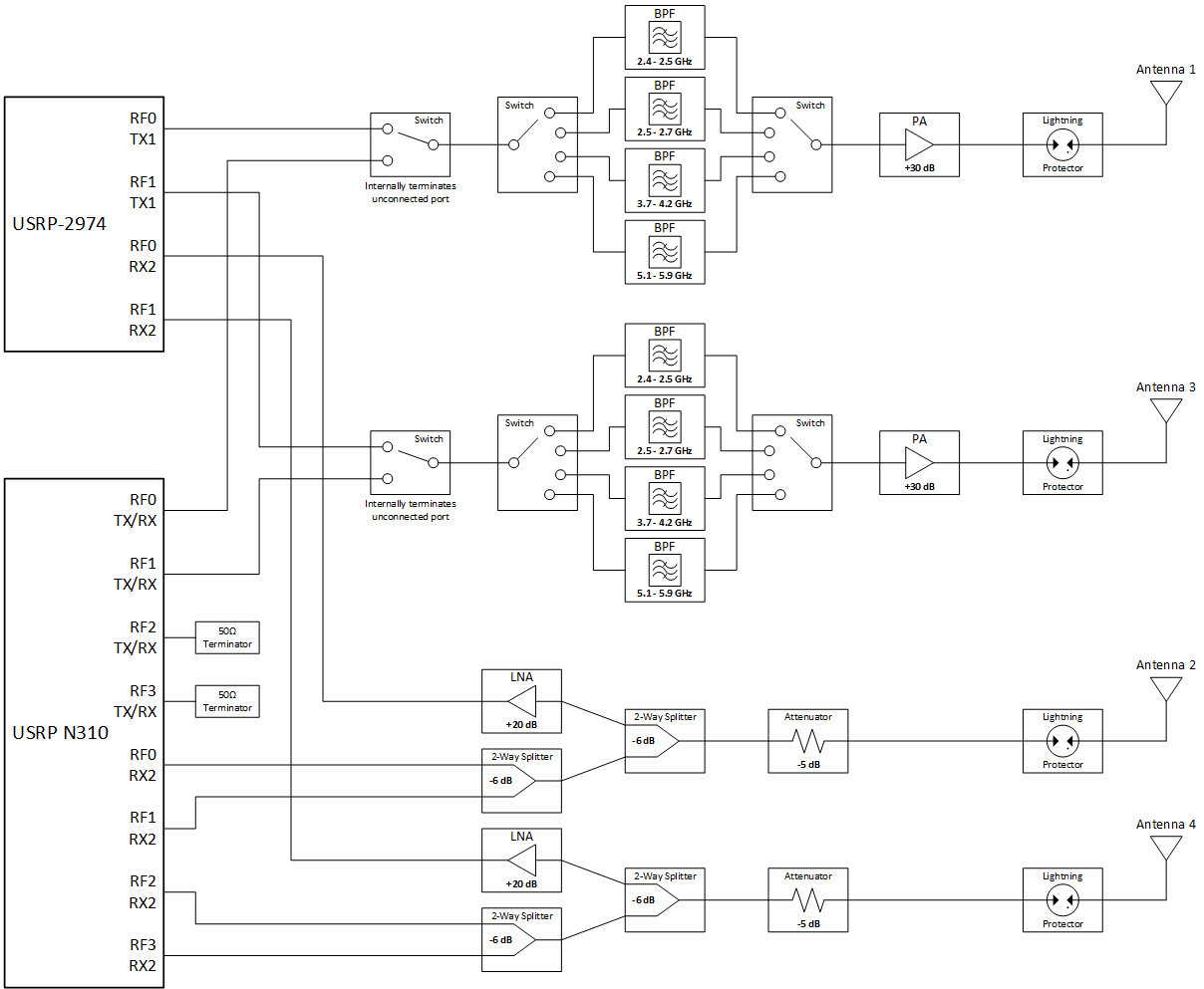
Each node has an RF front end situated between the USRPs and the antennas. This front end provides amplification, filtering, and other signal control functions. The diagram below shows a component level overview of the connections. Further details are provided in the following sections.

Transmit (TX) Chains
There are 2 user configurable transmit (TX) chains connected to the USRPs. Each TX chain has a power amplifier (PA) providing +30 dB of gain across 2-8 GHz with a maximum output power of +30 dBm (see datasheet for more details). There are several bands available for the TX chains (prior approval required for use of certain bands). Currently only one band can be selected for use across both TX chains. The allowed transmit frequency bands are detailed on the Policies Compliance page.
The TX chains are user configurable for connection to either the USRP N310 or the USRP 2974. It is possible to have both chains connected to one USRP or one chain per USRP as follows:
| Antenna 1 | Antenna 3 |
|---|---|
| N310 (RF0-TX) | N310 (RF1-TX) |
| N310 (RF0-TX) | 2974 (RF1-TX) |
| 2974 (RF0-TX) | N310 (RF1-TX) |
| 2974 (RF0-TX) | 2974 (RF1-TX) |
Please refer to the antenna section for antenna specific details.
NOTE: USRP N310 ports RF2-TX and RF3-TX are not connected at all. They are 50 ohm terminated at the USRP and should not be used.
Receive (RX) Chains
There are 2 receive (RX) chains connected to the USRPs at all times. No filtering is done on the RX chains, so any frequency can be monitored provided it is within the specifications of other system components (900 Mhz – 6 GHz for large node sector, 1.7-6 GHz for medium node). Only the connections to the USRP 2974 have low-noise amplifiers (LNA) connected due to the low maximum input power raing (-15 dBm) of the USRP N310 receive chains and the close proximity of the TX and RX antennas. All the RX2 ports of the USRPs are connected to the receive antennas as follows:
USRP 2974 Port Mapping:
| USRP Port | Antenna | Typical loss between antenna and USRP |
|---|---|---|
| RF0-RX2 | 2 | +10 dB (+21 dB LNA, -6 dB splitter, -5 dB attenuator) |
| RF1-RX2 | 4 | +10 dB (+21 dB LNA, -6 dB splitter, -5 dB attenuator) |
USRP N310 Port Mapping:
| USRP Port | Antenna | Typical loss between antenna and USRP |
|---|---|---|
| RF0-RX2 | 2 | -17 dB (-6 dB splitter, -6 dB splitter, -5 dB splitter) |
| RF1-RX2 | 2 | -17 dB (-6 dB splitter, -6 dB splitter, -5 dB splitter) |
| RF2-RX2 | 4 | -17 dB (-6 dB splitter, -6 dB splitter, -5 dB splitter) |
| RF3-RX2 | 4 | -17 dB (-6 dB splitter, -6 dB splitter, -5 dB splitter) |
Please refer to the antenna section for antenna specific details.
NOTE: Loss is “typical” value for reference only and does not take into account antenna gain or cable losses.
Attachments (3)
-
ZVE-8G+.pdf
(310.6 KB
) - added by 7 years ago.
ZVE-8G+ power amplifier - datasheet
-
ZX60-83LN12+.pdf
(311.6 KB
) - added by 7 years ago.
LNA datasheet
- sub6 rf front end - pilot.png (57.3 KB ) - added by 6 years ago.
Download all attachments as: .zip