Site Navigation
- COSMOS Testbed Overview
- Getting Started
- COSMOS/ORBIT User Guide
- COSMOS Portal
- Account Management
- Portal Dashboard
- Directory
- Disk Images
- Community Forum
- Getting Started with the COSMOS Portal
- SSH Access to Testbed Nodes
- Scheduler
- Testbed Status
- Installing Chrome Remote Desktop (CRD) on a Custom Image
- Tutorials
- Architecture
- Resources, Services and APIs
- Datasets
- Hardware Info
- RF Policies & Compliance
Setting up a Virtual / Simulated Optical Network using the Mininet-Optical Software Emulator
This wiki page contains a tutorial for setting up a virtual/simulated optical network using Mininet-Optical. Mininet-Optical was developed as part of the COSMOS and COSM-IC projects and adds optical network emulation and simulation capabilities to Mininet to support software emulation of optical and packet-optical networks, including modeling of optical transmission effects and impairments.
This is a Mininet-Optical version of the tutorial at Tutorials/Optical/Tutorial1 and is intended to show how an experiment designed for COSMOS' optical network testbed (hardware) may be adapted for use in a software emulation environment running on Linux (for example in a VM on a laptop or other hardware server), and how Mininet-Optical may be used to design experiments that will later be run on the COSMOS hardware testbed.
The Mininet-Optical version of this tutorial implements the same network topology and the same experiment as the hardware testbed tutorial, but there are differences between the software and hardware environments.
Please refer to Tutorials/Optical/Tutorial1 for comparison with the hardware environment.
Converted by: Bob Lantz
Original (hardware) tutorial Authors:
Artur Minakhmetov, Telecom Paris : artur.minakhmetov[at]telecom-paris.fr
Craig Gutterman, Columbia University : clg2168[at]columbia.edu
Michael Sherman, Rutgers University : msherman[at]winlab.rutgers.edu
Jiakai Yu, University of Arizona : jiakaiyu[at]email.arizona.edu
Tingjun Chen, Columbia University: tc2668[at]columbia.edu
Change Log
26 July 2022: Adapted hardware tutorial to Mininet-Optical for COSM-IC mini-tutorial.
Description
The COSMOS testbed enables creation and use of optical networks of various topologies. Similarly, Mininet-Optical enables creation of virtual optical networks using software emulation. An example of how an optical network could be configured and used is provided. A simple experiment on switching of optical paths is described.
Compute Nodes and ToR switch interfaces used
- Each compute node has 1 Ethernet interface:
server1-eth0
server2-eth0
server2-eth0
- There are three ToR Ethernet interfaces:
tor1-eth111
tor2-eth112
tor3-eth113
- and three WDM transceivers, with separate output and input ports:
tor1-wdm320/321
tor2-wdm290/291
tor3-wdm310/311
Experiment_1 Context

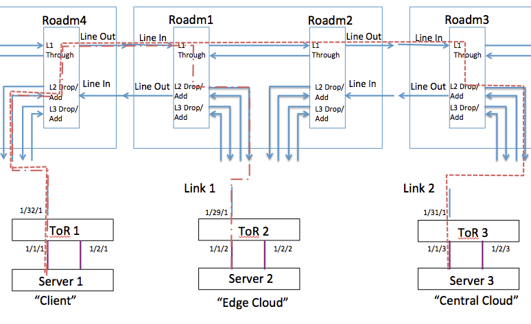
Fig.1 Logical Topology of Experiment_1
The experiment consists of changing the light path from ToR1←→ToR2 to ToR1←→ToR3, representing changing of the light path in a C-RAN when “Client” wants to move its base-band processing from “Edge Cloud” to “Central Cloud”.
Experiment includes 3 servers:
server1
server2
server3
Experiment includes 4 ROADMs:
roadm1 (localhost:1831)
roadm2 (localhost:1832)
roadm3 (localhost:1833)
roadm4 (localhost:1844)
3 ToR interfaces are connected to the 3 servers:
tor1-eth111 <--> server1
tor2-eth112 <--> server2
tor3-eth113 <--> server3
3 Ethernet interfaces and 3 WDM transceivers will be connected within the ToR switch:
tor1-eth111 ; tor1-wdm320/321  (output/input)
tor2-eth112 ; tor2-wdm290/291  (output/input)
tor3-eth113 ; tor3-wdm310/311  (output/input)
We are assigning the following wavelength to the transceivers:
1553.30 nm 193.00 THz with bandwidth ~[192.95;193.05] THz
This corresponds to channel 34 in Mininet-Optical's default channel grid.
Prerequisites: Installing Mininet-Optical
Before starting this tutorial, you will need to have Mininet-Optical installed. If it isn't installed already, you can follow the Installation and Walkthrough instructions at https://mininet-optical.org.
The tutorial topology and a sample configuration script should be found in ~/mininet-optical/examples/cosmostutorial.py and ~/mininet-optical/examples/config-cosmostutorial.sh. If they are not there, you may need to fetch and check out the appropriate cosmos-tutorial branch from github and install it using make install, as described below.
Setting Up the Optical Topology
In the COSMOS optical testbed, all devices are connected to a Calient S320 space switch. This switch serves as a programmable patch panel that allows any port to be connected to any other port, enabling realization of arbitrary topologies with fast reconnection between experiments.
It is possible to create a virtual space switch/programmable patch panel in Mininet-Optical to emulate the COSMOS optical testbed itself, but for this tutorial we will implement the topology using Mininet-Optical's topology API.
The Mininet-Optical emulated network is created using a Python script, examples/cosmostutorial.py. Take a look at it now to see how the topology is implemented.
The topology itself is created using Mininet's high-level topology template API. Specifically, we create a subclass of class Topo and override the build() method:
class TutorialTopo( Topo ):
...
    def build( self ):
ROADMs and ToR switches are added using addSwitch() calls:
        # ROADMs
        NC = NetconfPortBase
        roadm4 = self.addSwitch('roadm4', cls=LROADM, netconfPort=NC+4)
        ...
        # ToR switches
        tor1 = self.addSwitch('tor1', cls=Terminal, transceivers=[('32', 0*dBm)])
        ...
Servers are added using addHost() calls:
        # Servers
        server1 = self.addHost('server1')
        ...
In Mininet, ports are created by specifying port numbers when we add links.
(This is due to the underlying link emulation which uses Linux virtual Ethernet (veth)
pairs.)
Because of this, we need to specify the correct port numbers when we create the links.
The base port numbers for a Lumentum ROADM20 are specified at the top of the file:
# Lumentum Roadm20 Port numbering
LINEIN, LINEOUT = 5101, 4201
ADD, DROP = 4100, 5200
The server and ToR port numbers are as specified above.
WDM fiber links are unidirectional and are added using wdmLink() calls:
        # Inter-ROADM links
        # We put 22km of fiber between roadm2 and roadm3
        # Default fiber length is 1m if not specified
        self.wdmLink(roadm4, roadm1, LINEOUT, LINEIN)
        self.wdmLink(roadm1, roadm4, LINEOUT, LINEIN)
        self.wdmLink(roadm1, roadm2, DROP+1, ADD+1)  # passthrough
        self.wdmLink(roadm2, roadm1, DROP+1, ADD+1)  # passthrough
        # Sub-millisecond delays won't be accurate (due to scheduler timing
        # granularity and running in a VM) but this will add observable
        # propagation delay for the longer links.
        self.wdmLink(roadm2, roadm3, LINEOUT, LINEIN, spans=[22*km], delay='73us')
        self.wdmLink(roadm3, roadm2, LINEOUT, LINEIN, spans=[22*km], delay='73us')
        ...
        # ROADM add/drop 2 <-> ToR transceiver links
        self.wdmLink(tor1, roadm4, 320, ADD+2)
        self.wdmLink(roadm4, tor1, DROP+2, 321)
We can see that LINEOUT of roadm2 is connected to LINEIN of roadm3 and vice-versa,
with a 22km length of fiber in between, corresponding to a fiber spool in
the COSMOS testbed. Later, add/drop port 2 of roadm4 is connected to ports
320/321 of tor1 (output/input, respectively).
Ethernet links are added using addLink() calls:
        # Server<->ToR Ethernet links
        self.addLink(server1, tor1, port1=0, port2=1)
        self.addLink(server2, tor2, port1=0, port2=2)
        self.addLink(server3, tor3, port1=0, port2=3)
Lastly, the topology and network objects are instantiated and everything is started up (and shut down) in the __main__ section of the network setup script:
if __name__ == '__main__':
    ...
    topo = TutorialTopo()
    net = Mininet( topo=topo, controller=None )
    restServer = RestServer( net )
    net.start()
    restServer.start()
    netconfServer = NetconfServer(
        net, username=username, password=password, sslkeyfile=sslkeyfile )
    netconfServer.start()
    ...
    if 'test' in argv:
        test(net)
    else:
        info(TutorialTopo.__doc__+'\n')
        CLI(net)
    netconfServer.stop()
    restServer.stop()
    net.stop()
    info( 'Done.\n')
Creating the Mininet-Optical Network
All of these commands should be run in a terminal window for the VM or server where Mininet-Optical is installed.
We will run Mininet-Optical from the top directory of the source tree:
cd ~/mininet-optical
We should check to make sure that the tutorial scripts are present:
ls examples/cosmostutorial.py
ls examples/config-cosmostutorial.sh
If they are missing, we can fetch and install the appropriate branch:
git fetch
git checkout cosmos-tutorial
make install
Since the NETCONF agents for the ROADMs use SSL, we first have to generate a set of (self-signed) SSL certificates for them to use:
make certs
Now we should be able to run the tutorial script to create the emulated network:
sudo examples/cosmostutorial.py
(Note: if you want to use the X11 features of Mininet, such as the xterm or plot commands, you may need to use sudo HOME=~ rather than just sudo.)
This should start up Mininet-Optical, create the tutorial network, and start the CLI:
    COSM-IC mini-tutorial topology:

    roadm4 <-> roadm1 <-> roadm2 <-22km-> roadm3
     |          |                          |
    tor1       tor2                       tor3
     |          |                          |
    server1    server2                    server3

    This is for the COSMOS mini-tutorial at:
    https://wiki.cosmos-lab.org/wiki/Tutorials/Optical/MininetOpticalTutorial1

*** Starting CLI:
mininet-optical>
Mininet-Optical CLI commands may be entered at the mininet-optical> prompt.
If you don't have one open already, open up another terminal window and connect to the Linux VM or server where Mininet-Optical is installed. You may wish to enter the source directory in this window as well:
cd ~/mininet-optical
Unless specified otherwise, all of the configuration commands below should be entered in this second window at the shell prompt.
ROADM Configuration
All of these configurations can be performed by Python scripts developed to work with the COSMOS test-bed. The Python commands send NETCONF commands to the ROADM.
Setting “Snake” Connection
(This is not currently part of the Mininet-Optical software emulated configuration.)
Transceiver 33 (ports 330/331) on ToR configuration
(This is not currently part of the Mininet-Optical software emulated configuration, but it would be: 60 (DWDM Channel C60) 1529,55 nm 196,00 Thz with frequency range [195.95,196.05] Thz)
MUX/DEMUX configuration
As a reminder, here are the ROADM port numbers:
- ROADM 4:
DEMUX IN/OUT (ADD1/LINEOUT) port: 5101/5201 MUX IN/OUT (LINEIN/DROP1)port: 4101/4201
- ROADM 1:
DEMUX IN/OUT (ADD1/LINEOUT) port: 5101/5201 MUX IN/OUT (LINEIN/DROP1) port: 4101/4201
- ROADM 2:
DEMUX IN/OUT (ADD1/LINEOUT) port: 5101/5201 MUX IN/OUT (LINEIN/DROP1) port: 4101/4201
- ROADM 3:
DEMUX IN/OUT (ADD1/LINEOUT) port: 5101/5201 MUX IN/OUT (LINEIN/DROP1) port: 4101/4201
Note that the servers are connected to ADD2/DROP2 while DROP1/ADD1 are used as passthrough ports between ROADM 1 and ROADM 2.
Note also that these port numbers are different from what is on the hardware tutorial page but they are consistent with the configuration on that page.
ALS Disable Sequence (for 60 seconds)
(This is not currently done in the Mininet-Optical configuration.)
Configuring ROADMs in Mininet-Optical
ROADMs in Mininet-Optical may be configured via several mechanisms. An internal Python API may be used for configuration within the script that creates the network. More realistically, two external SDN/RPC control interfaces are provided: a simple REST interface and a more realistic NETCONF interface which is partially compatible with the NETCONF interface of the hardware Lumentum ROADM20.
Note that the REST API is specific to Mininet-Optical and is not supported in the hardware testbed.
For this tutorial, either the REST (simpler, but different from hardware) or NETCONF (more complicated but closer to the hardware testbed) may be used.
Setting “Experiment_1” Connections using REST
Configuring ToR1↔ToR2 Connection 1 on Mininet-Optical using REST
- ROADM 4:
- Enable MUX port 4102 “From ToR 1”
- Add Connection “Exp1-FromTor1” with Input/ Output Port 4102/4201 with bandwidth [192.95;193.05]
- Enable DEMUX port 5202 “Towards ToR 1”
- Add Connection “Exp1-TorwardTor1” with I/O Port 5101/5202
192.95THz..193.05THz has a middle frequency of 193.00 THz, which corresponds to channel C34 on Mininet-Optical's default 50GHz channel grid. C1's middle frequency is 191350 GHz, so C34 is at 191350 + 33*50 = 193000 GHz.
We use curl to send a REST request to roadm4 to add/drop channel 34:
    curl "localhost:8080/connect?node=roadm4&port1=4102&port2=4201&channels=34"
    curl "localhost:8080/connect?node=roadm4&port1=5101&port2=5202&channels=34"
- ROADM 1:
- Enable MUX port 4102 “From ToR 2”
- Add Connection “From ToR 2” with I/O Port 4102/4201 with bandwidth [192.95;193.05]
- Enable DEMUX port 5202 “Towards ToR 2”
- Add Connection “Towards ToR 2” with I/O Port 5101/5202
We use curl to send a REST request to roadm1 to add/drop channel 34:
    curl "localhost:8080/connect?node=roadm1&port1=4102&port2=4201&channels=34"
    curl "localhost:8080/connect?node=roadm1&port1=5101&port2=5202&channels=34"
Configuring ToR1↔ToR3 Connection 2 on Mininet-Optical using REST
- ROADM 4 (Same As For Connection 1):
- Enable MUX port 4102 “From ToR 1”
- Add Connection “From ToR 1” with I/O Port 4102/4201 with bandwidth [192.95;193.05]
- Enable DEMUX port 5202 “Towards ToR 1”
- Add Connection “Towards ToR 1” with I/O Port 5101/5202 with bandwidth [192.95;193.05]
    curl "localhost:8080/connect?node=roadm4&port1=4102&port2=4201&channels=34"
    curl "localhost:8080/connect?node=roadm4&port1=5101&port2=5202&channels=34"
- ROADM 1 <Not Same!>:
- Enable MUX port 4101 “Through Port” (enabled for Snake)
- Add Connection “Through In” with I/O Port 4101/4201 with bandwidth [192.95;193.05]
- Enable DEMUX port 5201 “Through Port” (enabled for Snake)
- Add Connection “Through Out” with I/O Port 5101/5201 with bandwidth [192.95;193.05]
This time we pass channel 34 through ROADM 1:
    curl "localhost:8080/connect?node=roadm1&port1=4101&port2=4201&channels=34"
    curl "localhost:8080/connect?node=roadm1&port1=5101&port2=5201&channels=34"
- ROADM 2 (Same As For ROADM1):
- Enable MUX port 4101 “Through Port” (enabled for Snake)
- Add Connection “Through In” with I/O Port 4101/4201 with bandwidth [192.95;193.05]
- Enable DEMUX port 5201 “Through Port” (enabled for Snake)
- Add Connection “Through Out” with I/O Port 5101/5201 with bandwidth [192.95;193.05]
And pass through ROADM2:
    curl "localhost:8080/connect?node=roadm2&port1=4101&port2=4201&channels=34"
    curl "localhost:8080/connect?node=roadm2&port1=5101&port2=5201&channels=34"
- ROADM 3 (Same As For ROADM4):
- Enable MUX port 4102 “From ToR 3”
- Add Connection “From ToR 3” with I/O Port 4102/4201 with bandwidth [192.95;193.05]
- Enable DEMUX port 5202 “Towards ToR 3”
- Add Connection “Towards ToR 3” with I/O Port 5101/5202 with bandwidth [192.95;193.05]
And we drop at ROADM3:
    curl "localhost:8080/connect?node=roadm3&port1=4102&port2=4201&channels=34"
    curl "localhost:8080/connect?node=roadm3&port1=5101&port2=5202&channels=34"
Setting “Experiment_1” Connections using NETCONF
Configuring ToR1↔ToR2 Connection 1 on Mininet-Optical using NETCONF
- ROADM 4:
- Enable MUX port 4102 “From ToR 1”
- Add Connection “Exp1-FromTor1” with Input/ Output Port 4102/4201 with bandwidth [192.95;193.05]
- Enable DEMUX port 5202 “Towards ToR 1”
- Add Connection “Exp1-TorwardTor1” with I/O Port 5101/5202
The NETCONF servers for roadm1-roadm4 are listening on localhost at ports 1831-1834, respectively.
We will use the examples/nc_add_connection.py script to configure connections using NETCONF.
Note that MUX/ADD/LINEOUT is module 1 and DEMUX/DROP/LINEIN is module 2. We are calling all of our
connections connection 10. The interfaces are in-service and blocked is false. The 5 is an
attenuation setting which may currently be ignored in Mininet-Optical.
examples/nc_add_connection.py localhost:1834 1 10 in-service false 4102 4201 192950 193050 5 Exp1-FromTor1
examples/nc_add_connection.py localhost:1834 2 10 in-service false 5101 5202 192950 193050 5 Exp1-TorwardTor1
- ROADM 1:
- Enable MUX port 4102 “From ToR 2”
- Add Connection “From ToR 2” with I/O Port 4102/4201 with bandwidth [192.95;193.05]
- Enable DEMUX port 5202 “Towards ToR 2”
- Add Connection “Towards ToR 2” with I/O Port 5101/5202
examples/nc_add_connection.py localhost:1831 1 10 in-service false 4102 4201 192950 193050 5 Exp1-FromTor2
examples/nc_add_connection.py localhost:1831 2 10 in-service false 5101 5202 192950 193050 5 Exp1-TorwardTor2
Configuring ToR1↔ToR3 Connection 2 on Mininet-Optical using NETCONF
- ROADM 4 (Same As For Connection 1):
- Enable MUX port 4102 “From ToR 1”
- Add Connection “From ToR 1” with I/O Port 4102/4201 with bandwidth [192.95;193.05]
- Enable DEMUX port 5202 “Towards ToR 1”
- Add Connection “Towards ToR 1” with I/O Port 5101/5202 with bandwidth [192.95;193.05]
examples/nc_add_connection.py localhost:1834 1 10 in-service false 4102 4201 192950 193050 5 Exp1-FromTor1
examples/nc_add_connection.py localhost:1834 2 10 in-service false 5101 5202 192950 193050 5 Exp1-TorwardTor1
- ROADM 1 <Not Same!>:
- Enable MUX port 4101 “Through Port” (enabled for Snake)
- Add Connection “Through In” with I/O Port 4101/4201 with bandwidth [192.95;193.05]
- Enable DEMUX port 5201 “Through Port” (enabled for Snake)
- Add Connection “Through Out” with I/O Port 5101/5201 with bandwidth [192.95;193.05]
This time we pass channel 34 through ROADM 1:
examples/nc_add_connection.py localhost:1831 1 10 in-service false 4101 4201 192950 193050 5 Exp1-EastR1
examples/nc_add_connection.py localhost:1831 2 10 in-service false 5101 5201 192950 193050 5 Exp1-WestR1
- ROADM 2 (Same As For ROADM1):
- Enable MUX port 4101 “Through Port” (enabled for Snake)
- Add Connection “Through In” with I/O Port 4101/4201 with bandwidth [192.95;193.05]
- Enable DEMUX port 5201 “Through Port” (enabled for Snake)
- Add Connection “Through Out” with I/O Port 5101/5201 with bandwidth [192.95;193.05]
And pass through ROADM2:
examples/nc_add_connection.py localhost:1832 1 10 in-service false 4101 4201 192950 193050 5 Exp1-WestR2
examples/nc_add_connection.py localhost:1832 2 10 in-service false 5101 5201 192950 193050 5 Exp1-EastR2
- ROADM 3 (Same As For ROADM4):
- Enable MUX port 4102 “From ToR 3”
- Add Connection “From ToR 3” with I/O Port 4102/4201 with bandwidth [192.95;193.05]
- Enable DEMUX port 5202 “Towards ToR 3”
- Add Connection “Towards ToR 3” with I/O Port 5101/5202 with bandwidth [192.95;193.05]
And we drop at ROADM3:
examples/nc_add_connection.py localhost:1833 1 10 in-service false 4102 4201 192950 193050 5 Exp1-FromTor2
examples/nc_add_connection.py localhost:1833 2 10 in-service false 5101 5202 192950 193050 5 Exp1-TorwardTor2
Network Interfaces Configuration for Experiment_1
Setting Up ToR switches and configuring transceivers
Mininet-Optical's Terminal is the equivalent of the ToR switch
which contains Ethernet interfaces as well as WDM transceivers.
Instead of using a Cisco-style CLI to configure it, we use its default REST API.
As noted above, 193.00 THz corresponds to channel C34 on Mininet-Optical's default 50GHz channel grid. C1's middle frequency is 191350 GHz, so C34 is at 191350 + 33*50 = 193000 GHz.
- Connect Ethernet interfaces to Transceivers and set channel
curl "localhost:8080/connect?node=tor1ðPort=1&wdmPort=320&wdmInPort=321&channel=34" curl "localhost:8080/connect?node=tor2ðPort=2&wdmPort=290&wdmInPort=291&channel=34" curl "localhost:8080/connect?node=tor3ðPort=3&wdmPort=310&wdmInPort=311&channel=34"
- Turn on all transceivers
curl "localhost:8080/turn_on?node=tor1"
curl "localhost:8080/turn_on?node=tor2"
curl "localhost:8080/turn_on?node=tor3"
Configuring Compute Nodes (server1, server2, server3)
- Configure Ethernet interfaces and assign IP addresses:
This may be performed in at the mininet-optical> CLI prompt:
mininet-optical> server1 ifconfig server1-eth0 192.168.1.1/24
mininet-optical> server2 ifconfig server2-eth0 192.168.1.2/24
mininet-optical> server3 ifconfig server3-eth0 192.168.1.3/24
Or it can be done remotely from a shell prompt in the VM using the
~/mininet/util/m script:
~/mininet/util/m server1 ifconfig server1-eth0 192.168.1.1/24
~/mininet/util/m server2 ifconfig server2-eth0 192.168.1.2/24
~/mininet/util/m server3 ifconfig server3-eth0 192.168.1.3/24
Note that ~/mininet/util/m can be used to 'log in' to any one of the servers much as you would with ssh (but it actually spawns a shell in the appropriate cgroup/network namespace.)
Perform Experiment_1
- Establish Connection ToR1↔ToR2.
- Try
pingfromserver1toserver2:
mininet-optical> server1 ping 192.168.1.2
PING 192.168.1.2 (192.168.1.2) 56(84) bytes of data.
64 bytes from 192.168.1.2: icmp_seq=1 ttl=64 time=0.068 ms
64 bytes from 192.168.1.2: icmp_seq=2 ttl=64 time=0.062 ms
64 bytes from 192.168.1.2: icmp_seq=3 ttl=64 time=0.089 ms
^C
--- 192.168.1.2 ping statistics ---
3 packets transmitted, 3 received, 0% packet loss, time 2043ms
rtt min/avg/max/mdev = 0.062/0.073/0.089/0.011 ms
- Establish Connection ToR1↔ToR3.
- Try
pingfromserver1toserver3.
mininet-optical> server1 ping 192.168.1.3
PING 192.168.1.3 (192.168.1.3) 56(84) bytes of data.
64 bytes from 192.168.1.3: icmp_seq=1 ttl=64 time=0.354 ms
64 bytes from 192.168.1.3: icmp_seq=2 ttl=64 time=0.292 ms
64 bytes from 192.168.1.3: icmp_seq=3 ttl=64 time=0.363 ms
^C
--- 192.168.1.3 ping statistics ---
3 packets transmitted, 3 received, 0% packet loss, time 2052ms
rtt min/avg/max/mdev = 0.292/0.336/0.363/0.031 ms
Observe the slightly longer RTT to server3, reflecting the increased propagation time across two 22km fibers to reach the "Central Cloud" data center.
(Note that the Mininet-Optical ROADM dataplane is currently modeled using OvS switching in the Linux kernel, so each hop will add some delay that would not be seen on hardware. Process scheduling, OS and VM overhead, etc. can create additional delays in a software emulator.)
Shutting down Mininet-Optical
To exit Mininet-Optical, type exit or press control-D at the mininet-optical> prompt.
Acknowledgments
This tutorial is based on the hardware tutorial at Tutorials/Optical/Tutorial1 by T. Chen et al..
Mininet-Optical was developed by the Mininet-Optical project team including Bob Lantz, Alan Díaz, Jiakai Yu, Aamir Quraishy, Atri Mukhopadhyay, Julie Raulin, and Emmanuel Akinrintoyo, supervised by Dan Kilper, Bob Lantz, Marco Ruffini, and Fátima Gunning.
References
COSMOS Optical Hardware Testbed Tutorial 1: Tutorials/Optical/Tutorial1
Mininet-Optical Tutorial 1 network script: https://github.com/Mininet-Optical/mininet-optical/blob/cosmos-tutorial/mnoptical/examples/cosmostutorial.py
Mininet-Optical Tutorial 1 configuration script: https://github.com/Mininet-Optical/mininet-optical/blob/cosmos-tutorial/mnoptical/examples/config-cosmostutorial.sh
Mininet-Optical documentation: https://mininet-optical.org
Mininet-Optical code: https://github.com/mininet-optical/mininet-optical
(Packet) Mininet web site: https://mininet.org
Attachments (1)
- Experiment_1.png (83.0 KB ) - added by 4 years ago.
Download all attachments as: .zip