| Version 3 (modified by , 11 months ago) ( diff ) |
|---|
Site Navigation
- COSMOS Testbed Overview
- Getting Started
- COSMOS/ORBIT User Guide
- COSMOS Portal
- Account Management
- Portal Dashboard
- Directory
- Disk Images
- Community Forum
- Getting Started with the COSMOS Portal
- SSH Access to Testbed Nodes
- Scheduler
- Testbed Status
- Installing Chrome Remote Desktop (CRD) on a Custom Image
- Tutorials
- Architecture
- Resources, Services and APIs
- Datasets
- Hardware Info
- RF Policies & Compliance
Generating and Observing Basic FR3 Sine Wave
This experiment transmits a single-tone (sine) IF at 1.5 GHz from a USRP-2974 (Krypton) into a Pi-Radio FR3 front-end, which up-converts to an FR3 carrier (example: 10 GHz). A second Pi-Radio front-end down-converts the over-the-air signal back to 1.5 GHz for a USRP-2974 receiver, where a simple ASCII DFT spectrum viewer is used to verify the tone. The Pi-Radio web UI is used to configure the FR3 conversion.
Prerequisites
- COSMOS account and active reservation in Sandbox 1.
- Familiarity with USRP-2974 (embedded X310, 10 MHz–6 GHz, 160 MHz BW).
- FR3 hardware access (2× Pi-Radio FR3 front-ends) and the fr3-tutorials.ndz disk image for the USRPs.
Resources required
- Nodes: sdr1-piradio, sdr2-piradio, rfdev-sdr1-piradio, rfdev-sdr2-piradio.
- Antennas: 2× Vivaldi (Tx/Rx) connected to the Pi-Radio front-ends. (See FR3 hardware pages for antenna layout.)
- Browser access to Pi-Radio web UI on the rfdev-* nodes (port 5006).
Tutorial Setup ===
Follow the steps below to gain access to the sandbox 1 console and set up nodes with appropriate images.
- If you don't have one already, sign up for a COSMOS account
- Create a resource reservation on COSMOS sandbox 1
- Login into sandbox 1 console (console.sb1.cosmos-lab.org) with an SSH sessions.
- Make sure all the resources in the domain are turned off:
omf tell -a offh -t system:topo:allres
- Load fr3-tutorials.ndz on sdr1-piradio and sdr2-piradio nodes.
omf load -i fr3-tutorials.ndz -t sdr1-piradio,sdr2-piradio
- Turn all the required resources (2 USRPs and 2 Pi-Radio SDRs) on:
omf tell -a on -t sdr1-piradio,sdr2-piradio,rfdev-sdr1-piradio,rfdev-sdr2-piradio
- Check the node status to confirm that the nodes are up.
omf stat -t sdr1-piradio,sdr2-piradio,rfdev-sdr1-piradio,rfdev-sdr2-piradio
- After a minute (giving internal PCs enough time to boot), ssh to the USRP 2974s nodes and start the chrome remote desktop session (follow the instructions for setting remote access).
- Open a Chrome browser sessions in each of the two CDRs and access the Pi-Radio configuration pages
 https://sdr1-piradio.sb1.cosmos-lab.org:5006
 https://sdr2-piradio.sb2.cosmos-lab.org:5006
Experiment Execution
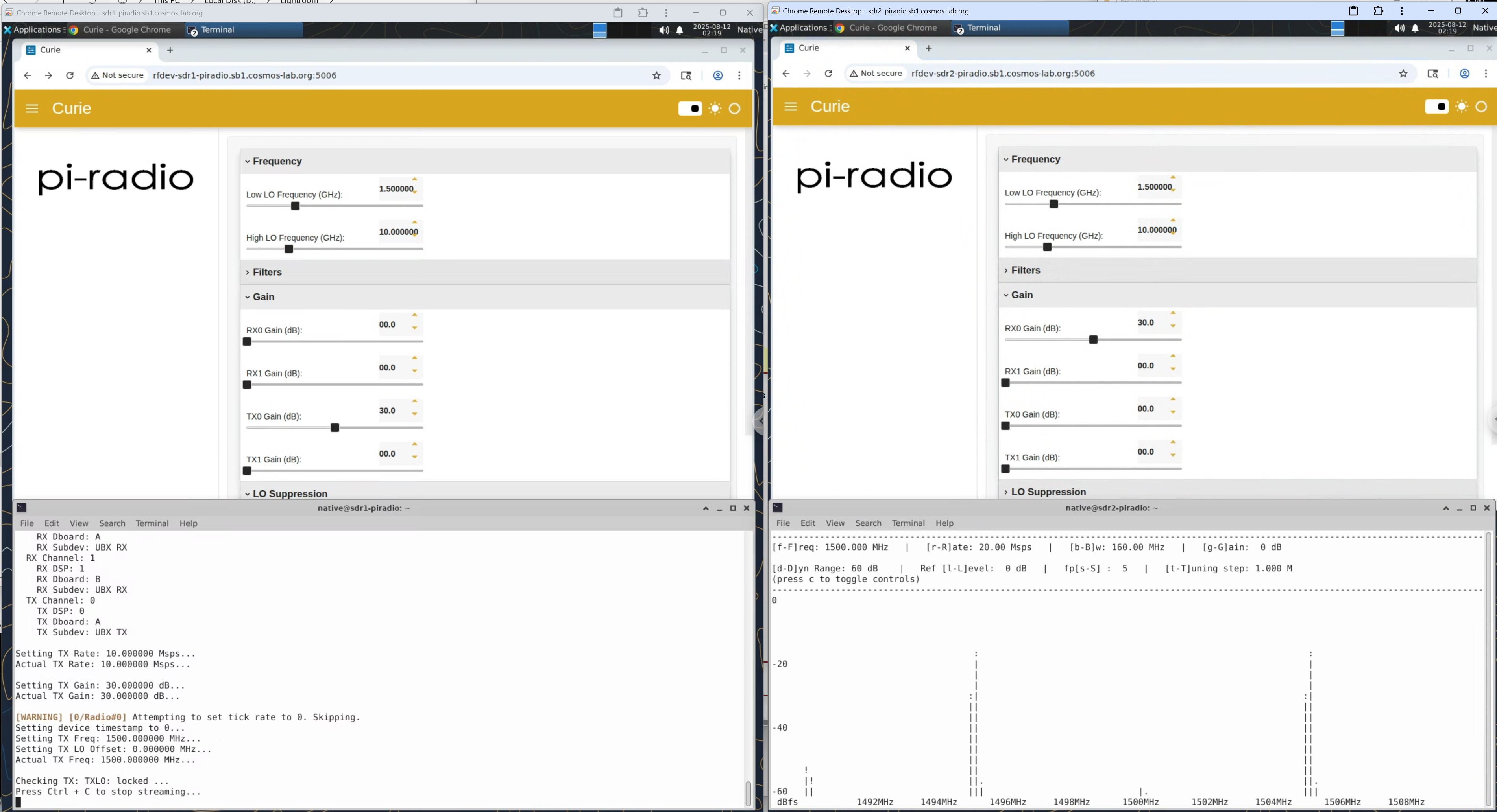
Use the Pi-Radio web UI Frequency panel on both rfdev pages (Tx and Rx) and set:
- Low LO Frequency (GHz): 1.500000
- High LO Frequency (GHz): 10.000000
This example pairs a 1.5 GHz IF with a 10 GHz high-side LO (and a 1.5 GHz low-side LO) to place the RF tone at ~10 GHz, and back to 1.5 GHz on the receive path. (Exact placement depends on mixer sign/paths; the screenshot below shows the working settings used in this demo.) Leave Filters, Gain (except where noted), and LO Suppression at defaults for the first run
On the transmitter (sdr1-piradio), start a 1.5 GHz sine at 5 MHz baseband tone:
tx_waveforms --args "resource=RIO0" --subdev A:0 --freq 1.5e9 --ampl 0.7 --gain 30 --wave-type SINE --ant TX/RX --rate 10e6 --wave-freq 5e6
On sdr2-piradio start the character based spectrum analyzer:
rx_ascii_art_dft --args "resource=RIO0" --subdev A:0 --freq 1.5e9 --ant RX2 --rate 20e6
You should observe a stable, narrow spectral line(s) in the DFT display near the configured tone at 5MHz (with side-markers set by the viewer). The figure below shows both Pi-Radio UIs (left: Tx FE, right: Rx FE) with Low LO = 1.5 GHz and High LO = 10 GHz, the TX console (bottom-left) and the ASCII DFT (bottom-right) around 1.5 GH

Attachments (1)
- pi-sine.png (1.9 MB ) - added by 11 months ago.
Download all attachments as: .zip