Site Navigation
- COSMOS Testbed Overview
- Getting Started
- COSMOS/ORBIT User Guide
- COSMOS Portal
- Account Management
- Portal Dashboard
- Directory
- Disk Images
- Community Forum
- Getting Started with the COSMOS Portal
- SSH Access to Testbed Nodes
- Scheduler
- Testbed Status
- Installing Chrome Remote Desktop (CRD) on a Custom Image
- Tutorials
- Architecture
- Resources, Services and APIs
- Datasets
- Hardware Info
- RF Policies & Compliance
802.11ad Preamble Processing blocks on COSMOS SandBox1
Upgrade in Progress
Description
This tutorial describes how to use RFNoC 802.11ad preamble processing blocks with Sivers 60GHz front-ends on COSMOS SandBox1. RFNoC 802.11ad preamble processing blocks demonstrated in this tutorial were developed by researchers at IMDEA networks institute, Spain, as an extension for EU project ORCA https://www.orca-project.eu/orca-at-the-imec-technology-forum. The extension was named MIllimeter wave SDR based Open experimentation platform (MISO), and the focus was on developing hardware/software for mmWave experimentation on SDRs. Specifically FPGA modules for processing 802.11ad(SC) preamble at scaled down bandwidth were designed and integrated with RFNoC, GNURadio, to be used on USRP X310s. Detailed information about the project can be found at https://www.orca-project.eu/millimeter-wave-open-experimentation-platform/.

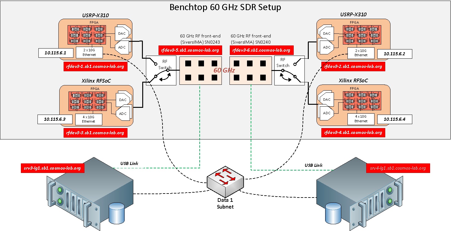
Setup for the experiment is shown in the figure above. In the benchtop 60GHz setup of SandBox1, either USRP X310 or RFSoC ZCU111 can be used for baseband processing. RF Switch boxes as shown in the figure are used to select between X310 and RFSoC. RF switch commands are explained at wiki:/Resources/Services/RFSwitch . To select X310s as baseband processing units, all the switches in the RF switch boxes are configured to port 1.
This experiment uses USRP X310s for baseband processing. Sivers control software on host servers, srv1-in1, srv1-in2 talks to the mmWave front-ends over USB links. Host GNURadio applications on the servers, send/receive data samples to/from the X310s over 10G Ethernet links. 802.11ad single carrier frames at reduced bandwidth (200MHz) are transmitted over 60GHz mmWave link, and channel impulse response is computed on the receive end.
Prerequisites
In order to access the test bed, create a reservation and have it approved by the reservation service. Access to the resources is granted after the reservation is confirmed. Please follow the process shown on the COSMOS work flow page to get started.
Resources required
2 servers srv1-in1, srv1-in2, 2 USRP X310s sdr4-in1, sdr4-in2 and both the Sivers mmWave platforms rfdev3-in1, rfdev3-in2 in COSMOS SB1. 2 servers srv3-lg1, srv4-lg1, 2 USRP X310s rfdev3-1, rfdev3-2, and both the Sivers platforms rfdev3-5, rfdev3-6 on COSMOS SB1.
Tutorial Setup
Follow the steps below to gain access to the sandbox 1 console and set up nodes with appropriate images.
- If you don't have one already, sign up for a COSMOS account
- Create a resource reservation on sandbox 1
- Login into sandbox 1 console (console.sb1.cosmos-lab.org) with two SSH sessions.
- Make sure all resources in the domain are turned off:
omf tell -a offh -t system:topo:allres
- The image rfnoc_wigig.ndz has aforementioned RFNoC 802.11ad preamble processing blocks and Sivers control software installed.
Load rfnoc_wigig.ndz on srv1-in1, srv1-in2.
omf load -i rfnoc_wigig.ndz -t srv1-in1,srv1-in2
- Turn all the required resources on and check the status
omf tell -a on -t srv1-in1,srv1-in2,sdr4-in1,sdr4-in2,rfdev3-in1,rfdev3-in2
omf stat -t system:topo:allres
- Make sure the RF switch boxes are configured to use X310s (all switches set to port 1)
root@console:~# curl am1.cosmos-lab.org:5054/rf_switch/status?name=rfsw1.sb1.cosmos-lab.org,rfsw2.sb1.cosmos-lab.org

<response status="OK">
  <rf_switch name="rfsw1.sb1.cosmos-lab.org" num_of_switches="4">
    <switch number="1" port="1"/>
    <switch number="2" port="1"/>
    <switch number="3" port="1"/>
    <switch number="4" port="1"/>
  </rf_switch>
  <rf_switch name="rfsw2.sb1.cosmos-lab.org" num_of_switches="4">
    <switch number="1" port="1"/>
    <switch number="2" port="1"/>
    <switch number="3" port="1"/>
    <switch number="4" port="1"/>
  </rf_switch>
</response>
- If some or all the ports are set to "2", set them to port "1"
curl "am1.cosmos-lab.org:5054/rf_switch/set?name=rfsw1.sb1.cosmos-lab.org,rfsw2.sb1.cosmos-lab.org&switch=1,2,3,4&port=1" - ssh to the nodes, use option -Y for using GUI.
Experiment Execution
Find and prepare USRPs
- The IP addresses for Ethernet Ports(Port 0, 10G with XG image) on the X310s sdr4-in1 and sdr4-in2 were hard-coded to 10.38.14.1 and 10.38.14.2 respectively. To access them from srv1-in1 or srv1-in2, configure the data1 network interfaces on srv1-in1 and srv1-in2 to 10.38.1.3 and 10.38.1.4 respectively.
root@srv1-in1:~# ifconfig data1 10.38.1.3 netmask 255.255.0.0 mtu 9000 up
root@srv1-in2:~# ifconfig data1 10.38.1.4 netmask 255.255.0.0 mtu 9000 up
- Run uhd_find_devices to check if the X310s can be reached
root@srv3-lg1:~# uhd_find_devices --args="addr=10.39.6.1"
[INFO] [UHD] linux; GNU C++ version 7.4.0; Boost_106501; UHD_3.14.1.1-release
--------------------------------------------------
-- UHD Device 0
--------------------------------------------------
Device Address:
    serial: 31B6FFA
    addr: 10.39.6.1
    fpga: XG
    name: rfdev3-1
    product: X310
    type: x300
- Check which RFNoC blocks are loaded on the X310s, by running uhd_usrp_probe
root@srv3-lg1:~# uhd_usrp_probe --args="addr=10.39.6.1"
- Following is the list of RFNoC blocks required for the experiment
|   |   |       RFNoC blocks on this device:
|   |   |
|   |   |   * DmaFIFO_0
|   |   |   * Radio_0
|   |   |   * Radio_1
|   |   |   * PacketDetector_0
|   |   |   * CFOC_0
|   |   |   * DDC_0
|   |   |   * DUC_0
|   |   |   * FIR_0
|   |   |   * SymbolTiming_0
|   |   |   * BoundaryDetector_0
|   |   |   * CIR_0
|   |   |   * FIFO_0
|   |   |   * FIFO_1
- If the required RFNoC blocks are not found, load X310 with MISO_IMAGE_x300.bit
root@srv3-lg1:~# uhd_image_loader --args="addr=10.39.6.1,type=x300" --fpga-path="ORCA_MISO_PROJECT/FPGA_IMAGES/MISO_IMAGE_x300.bit"
- Power cycle X310 to use the new image, and run uhd_usrp_probe to check RFNoC blocks.
root@console:~# omf tell -a offh -t rfdev3-1root@console:~# omf tell -a on -t rfdev3-1
Prepare Sivers 60GHz front-ends
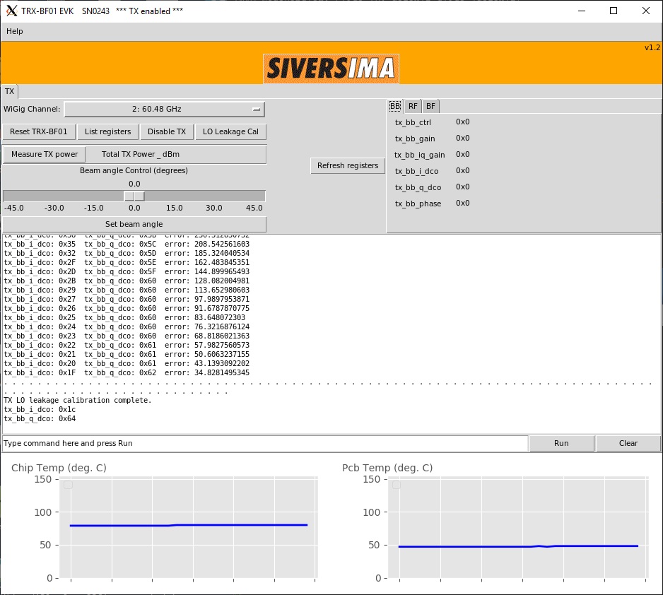
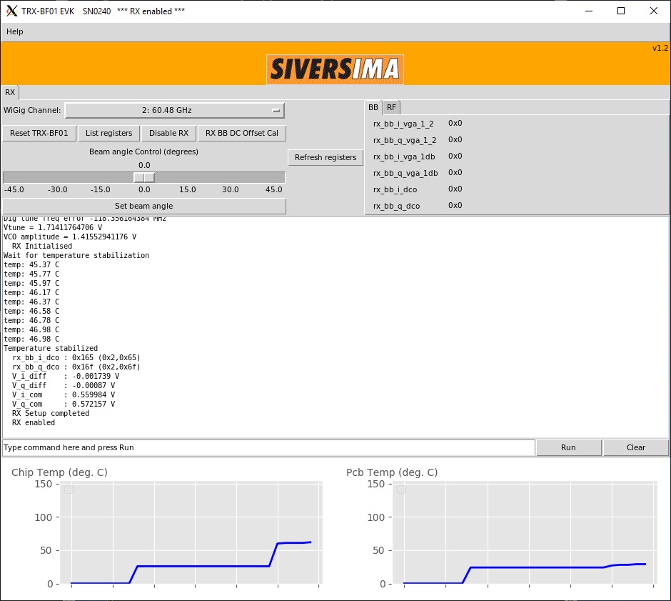
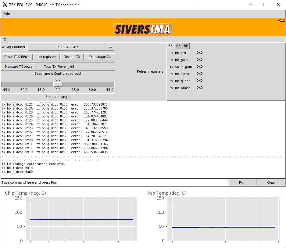
- To demonstrate the experiment here, we use Sivers front-end SN0240 as transmitter and SN0243 as receiver
| SN0240 as transmitter | SN0243 as receiver |
| root@srv4-lg1:~/ederenv# ./start_mb1.sh —gui SN0240 | root@srv3-lg1:~/ederenv# ./start_mb1.sh —gui SN0243 |
| Click "TX enable" and "LO leakage Cal" | Click "RX enable" |
 | 
|
Run the experiment
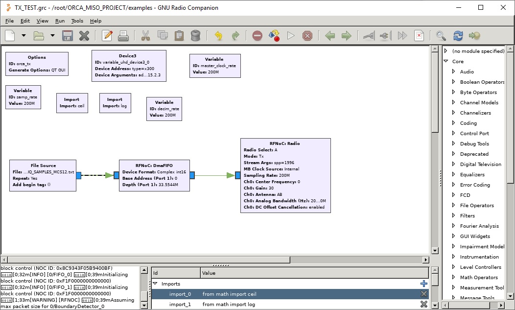
- Open transmit application TX_TEST.grc on transmit node(srv4-lg1). This application transmits 802.11ad frames over rfdev3-2(10.39.6.2), at 200MSPS, by reading samples from a pre-generated file.
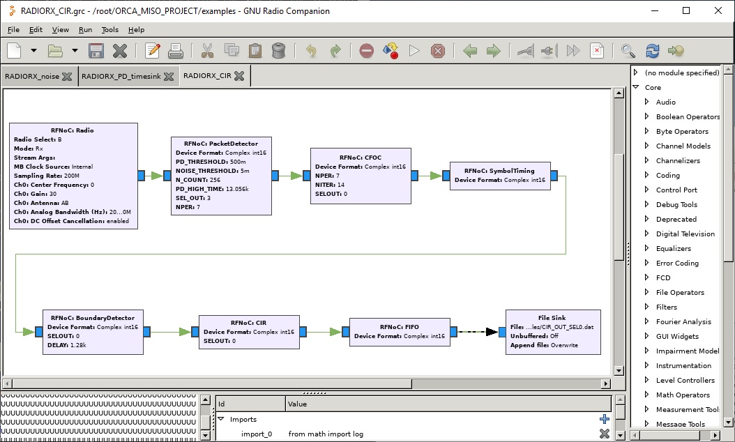
- Open receive application RADIORX_CIR.grc on receive node(srv3-lg1). This application receives and processes samples over rfdev3-1(10.39.6.1) as seen in the grc model below. Channel impulse response computed for every frame is written into a file on the host node.
| root@srv4-lg1:~# gnuradio-companion ORCA_MISO_PROJECT/examples/TX_TEST.grc | root@srv3-lg1:~# gnuradio-companion ORCA_MISO_PROJECT/examples/RADIORX_CIR.grc |
 | 
|
- Run TX applications followed by the RX application.
- Launch octave and plot the CIR using ORCA_MISO_PROJECT/examples/CIR_read_out_file.m
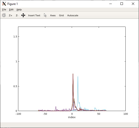
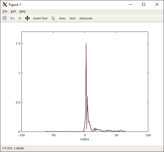
- Shown below are the CIR plots obtained for TX beam angles set to 0 and -5 degrees.
| TX beam angle 0 | TX beam angle -5 |
 | 
|
Attachments (9)
- Sivers_TX_GUI.jpg (174.4 KB ) - added by 6 years ago.
- Sivers_RX_GUI.jpg (126.9 KB ) - added by 6 years ago.
- Sivers_RX_SN0243.jpg (128.2 KB ) - added by 6 years ago.
- Sivers_TX_SN0240.jpg (162.6 KB ) - added by 6 years ago.
- radiorx_cir_grc.jpg (204.4 KB ) - added by 6 years ago.
- tx_test_grc.jpg (165.9 KB ) - added by 6 years ago.
- CIR_0.jpg (33.2 KB ) - added by 6 years ago.
- CIR_neg5.jpg (32.8 KB ) - added by 6 years ago.
- MISO_tutorial.jpg (256.2 KB ) - added by 6 years ago.
Download all attachments as: .zip