| Version 11 (modified by , 6 years ago) ( diff ) |
|---|
Site Navigation
- COSMOS Testbed Overview
- Getting Started
- COSMOS/ORBIT User Guide
- COSMOS Portal
- Account Management
- Portal Dashboard
- Directory
- Disk Images
- Community Forum
- Getting Started with the COSMOS Portal
- SSH Access to Testbed Nodes
- Scheduler
- Testbed Status
- Installing Chrome Remote Desktop (CRD) on a Custom Image
- Tutorials
- Architecture
- Resources, Services and APIs
- Datasets
- Hardware Info
- RF Policies & Compliance
Using Sivers mmWave equipment on COSMOS SandBox1
Description
A pair of Sivers EVK06002s, evaluation kits for Sivers IMA TRX BF/01, are deployed on COSMOS SandBox1. TRX BF/01 is a 16+16 IEEE802.11ad Beamforming Transceiver with a complete Radio front-end with 57-66 GHz mmWave frequency range. This tutorial demonstrates how to transmit and receive a signal in the 60GHz mmWave spectrum using these Sivers front-ends.
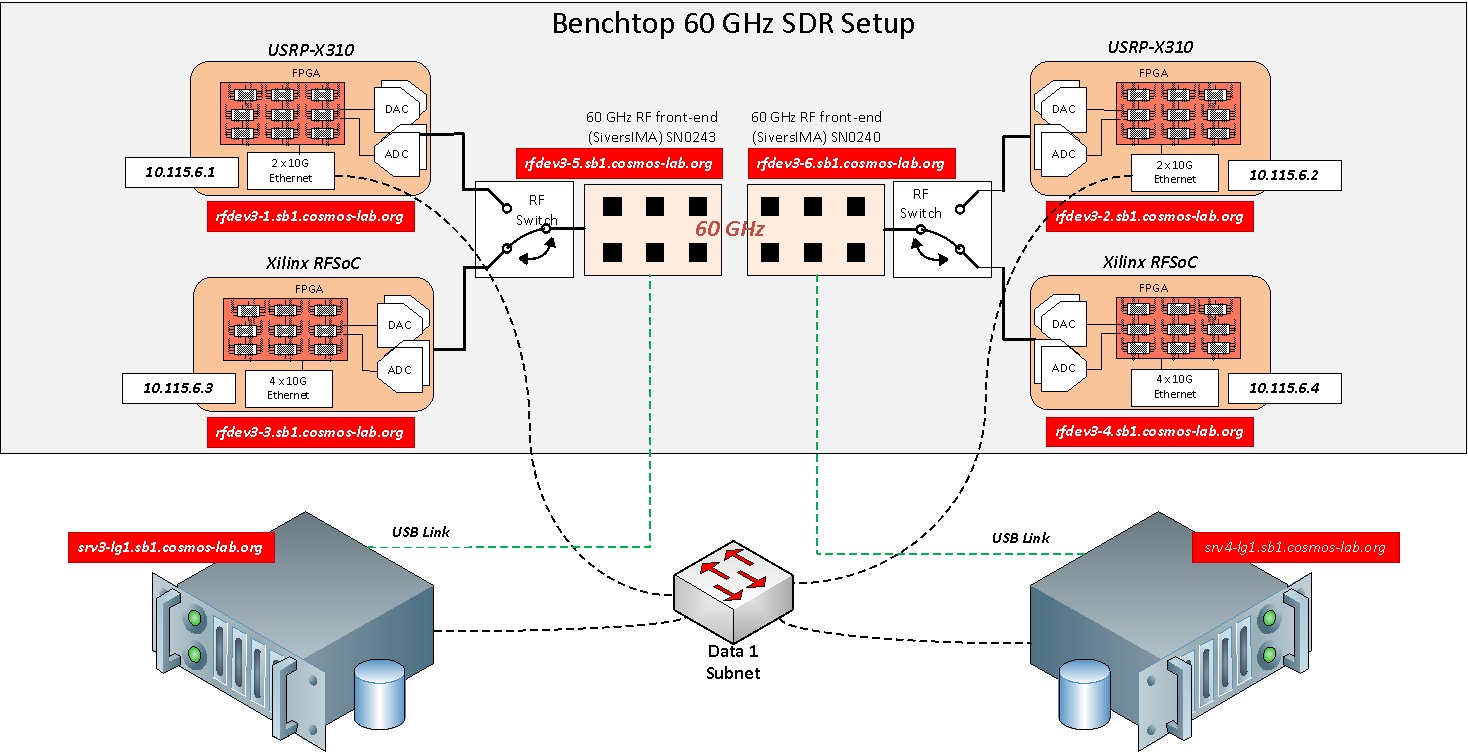
Current mmWave setup in COSMOS SB1 looks as shown in the figure below.

|
In the benchtop 60GHz setup of SandBox1, either USRP X310 or RFSoC ZCU111 can be used for baseband processing. RF Switch boxes as shown in the figure are used to select between X310 and RFSoC. RF switch commands are explained at wiki:/Resources/Services/RFSwitch. To select ZCU111 as baseband processing units, all the switches in the RF switch boxes are configured to port 2.
This experiment uses the Xilinx ZynqMP Ultrascale+ RFSoC ZCU111 board for the baseband processing. Sivers control software on srv3, srv4 talk to the mmWave front-ends over USB links. Host GNURadio applications on srv3, srv4, send/receive data samples to/from the RFSoC over 1G Ethernet link.
Prerequisites
In order to access the test bed, create a reservation and have it approved by the reservation service. Access to the resources is granted after the reservation is confirmed. Please follow the process shown on the COSMOS getting started page to get started.
Resources required
2 servers srv3-lg1, srv4-lg1, 2 Xilinx RFSoCs rfdev3-3, rfdev3-4 and both the Sivers platforms rfdev3-5, rfdev3-6 on COSMOS SB1.
Tutorial Setup
Follow the steps below to gain access to the sandbox 1 console and set up nodes with appropriate images.
- If you don't have one already, sign up for a COSMOS account
- Create a resource reservation on sandbox 1
- Login into sandbox 1 console (console.sb1.cosmos-lab.org) with two SSH sessions.
- Make sure all the nodes and devices of this reservation are turned off:
omf tell -a offh -t system:topo:allres
- The image rfsoc_sivers_sb1.ndz is [baseline_uhd.ndz] with Sivers control software and the Xilinx XSCT software installed
Load rfsoc_sivers_sb1.ndz on srv3,srv4.
omf load -i rfsoc_sivers_sb1.ndz -t srv3-lg1,srv4-lg1
- Turn all the required resources on and check the status
omf tell -a on -t srv3-lg1,srv4-lg1,rfdev3-3,rfdev3-4,rfdev3-5,rfdev3-6
- Check that the nodes are turned on
omf stat -t system:topo:allres
- Make sure the RF switch boxes are configured to use RFSoCs (all switches set to port 2)
root@console:~# curl am1.cosmos-lab.org:5054/rf_switch/status?name=rfsw1.sb1.cosmos-lab.org,rfsw2.sb1.cosmos-lab.org

<response status="OK">
  <rf_switch name="rfsw1.sb1.cosmos-lab.org" num_of_switches="4">
    <switch number="1" port="2"/>
    <switch number="2" port="2"/>
    <switch number="3" port="2"/>
    <switch number="4" port="2"/>
  </rf_switch>
  <rf_switch name="rfsw2.sb1.cosmos-lab.org" num_of_switches="4">
    <switch number="1" port="2"/>
    <switch number="2" port="2"/>
    <switch number="3" port="2"/>
    <switch number="4" port="2"/>
  </rf_switch>
</response>
- If some or all the ports are set to "1", set them to port "2"
curl "am1.cosmos-lab.org:5054/rf_switch/set?name=rfsw1.sb1.cosmos-lab.org,rfsw2.sb1.cosmos-lab.org&switch=1,2,3,4&port=2" - ssh to the nodes, use option -Y for using GUI.
Experiment Execution
Configure the 10G interface
The IP addresses for Ethernet Port 1(10G) on the RFSoCs rfdev3-3 and rfdev3-4 are hard-coded to 10.115.6.3 and 10.115.6.4 respectively. To access them from srv3-lg1 or srv4-lg1, configure the network interface enp1s0 of srv3-lg1 to 10.115.1.3 and srv4-lg1 to 10.115.1.4, as follows
root@srv3-lg1:~# ip link set enp1s0 mtu 9000 up
root@srv3-lg1:~# ip addr add 10.115.1.3/16 dev enp1s0
root@srv3-lg1:~# ip addr show dev enp1s0
4: enp1s0: <BROADCAST,MULTICAST,UP,LOWER_UP> mtu 9000 qdisc mq state UP group default qlen 1000
    link/ether f4:52:14:83:b9:30 brd ff:ff:ff:ff:ff:ff
    inet 10.115.1.3/16 brd 10.115.255.255 scope global enp1s0
       valid_lft forever preferred_lft forever
    inet6 fe80::f652:14ff:fe83:b930/64 scope link
       valid_lft forever preferred_lft forever
Prepare RFSoC boards
We need to download the FPGA firmware, the linux image and the rootfs over the JTAG. We use the Xilinx XSCT tool to do that. Note that this process will take around 5-10'.
- Configure the FPGA firmware of the
rfdev3-3from thesrv3-lg1as follows:root@srv3-lg1:~# cd rfsoc/firmware/sb1_rfdev3_3/ root@srv3-lg1:~/rfsoc/firmware/sb1_rfdev3_3# xsct download_firmware.tcl
- Configure the FPGA firmware of the
rfdev3-4from thesrv4-lg1as follows:root@srv4-lg1:~# cd rfsoc/firmware/sb1_rfdev3_4/ root@srv4-lg1:~/rfsoc/firmware/sb1_rfdev3_4# xsct download_firmware.tcl
- You can connect to FPGA over a serial monitor as follows:
root@srv3-lg1:~# minicom -D /dev/ttyUSB5
root@srv4-lg1:~# minicom -D /dev/ttyUSB1
Prepare Sivers 60GHz front-ends
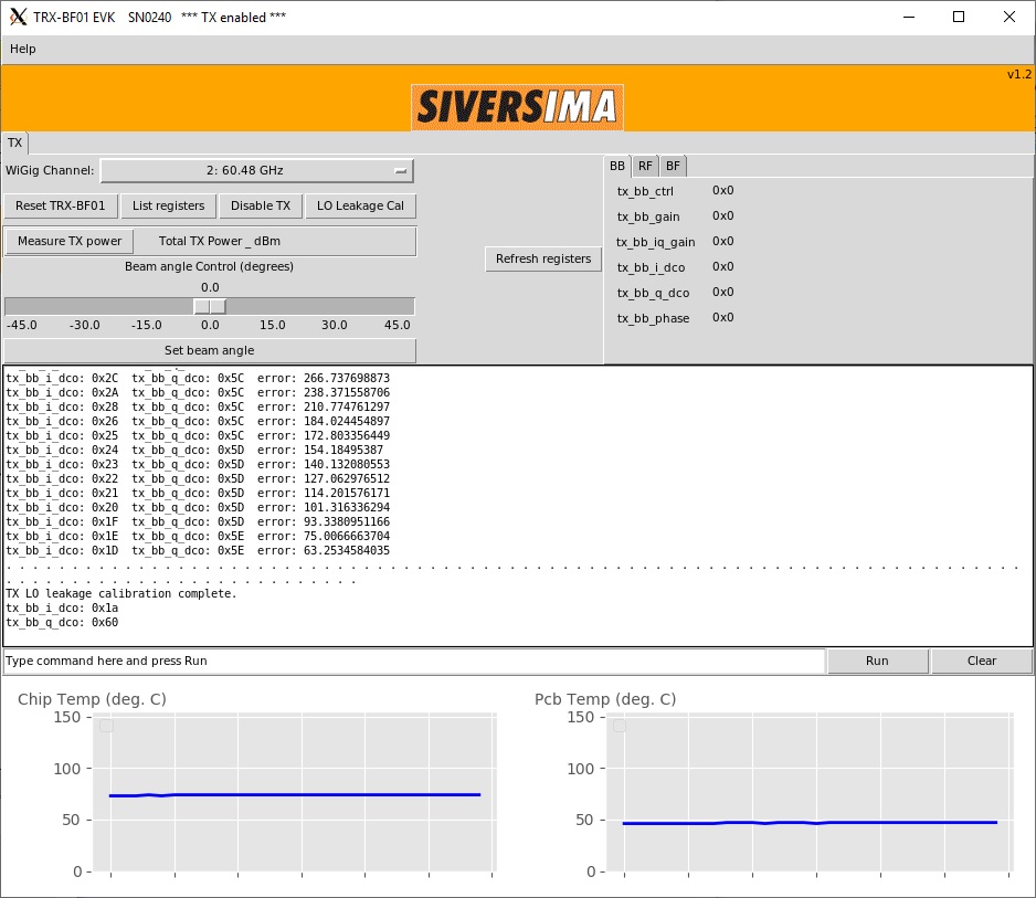
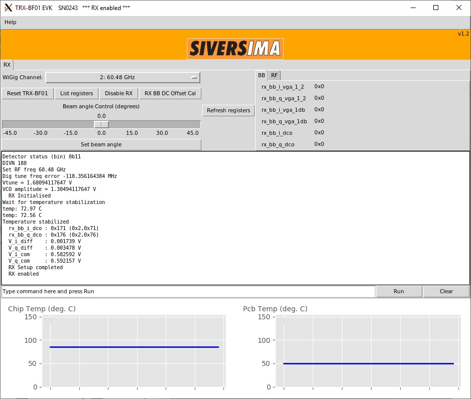
- To demonstrate the experiment here, we use Sivers front-end SN0240 as transmitter and SN0243 as receiver
| SN0240 as transmitter | SN0243 as receiver |
root@srv4-lg1:~/ederenv# ./start_mb1.sh --gui SN0240 | root@srv3-lg1:~/ederenv# ./start_mb1.sh --gui SN0243
|
| Click "Enable Tx" and "LO leakage Cal" | Click "Enable Rx" |
 | 
|
Execution
Run the experiment
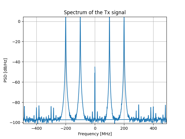
- Start the transmitter application on the TX node(srv4-lg1). Run the tx_waveforms python script in the examples folder:
root@srv4-lg1:~/rfsoc/examples# ./tx_waveforms
| Tx Waveform |

|
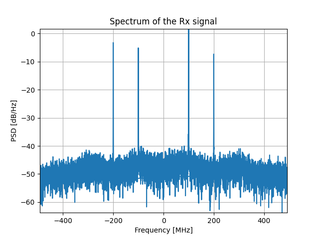
- Start the receiver application on the RX node(srv3-lg1). Run the rx_waveforms python script in the examples folder:
root@srv3-lg1:~/rfsoc/examples# ./rx_waveforms
| Rx Waveform |

|
Attachments (5)
- Sivers_TX_SN0240.jpg (162.6 KB ) - added by 6 years ago.
- Sivers_RX_SN0243.jpg (128.2 KB ) - added by 6 years ago.
- rfsoc_tx.png (43.1 KB ) - added by 6 years ago.
- rfsoc_rx.png (32.7 KB ) - added by 6 years ago.
- MISO_tutorial.jpg (256.2 KB ) - added by 6 years ago.
Download all attachments as: .zip