Site Navigation
- COSMOS Testbed Overview
- Getting Started
- COSMOS/ORBIT User Guide
- COSMOS Portal
- Account Management
- Portal Dashboard
- Directory
- Disk Images
- Community Forum
- Getting Started with the COSMOS Portal
- SSH Access to Testbed Nodes
- Scheduler
- Testbed Status
- Installing Chrome Remote Desktop (CRD) on a Custom Image
- Tutorials
- Architecture
- Resources, Services and APIs
- Datasets
- Hardware Info
- RF Policies & Compliance
Millimeter Wave Experimentation in COSMOS SB1 with Xilinx RFSoC
Upgrade in Progress
Authors:
- Panagiotis Skrimponis, New York University: ps3857[at]nyu.edu
- Prasanthi Maddala, Rutgers University
Last updated: October 18, 2021
Summary
Publications
For more information about the integration of the advanced programmable and open-source millimeter wave array systems in COSMOS, please read:
- T. Chen, P. Maddala, P. Skrimponis, J. Kolodziejski, X. Gu, A. Paidimarri, S. Rangan, G. Zussman, and I. Seskar, "Programmable and open-access millimeter-wave radios in the PAWR COSMOS testbed," in Proc. ACM Mobicom'21 Workshop on Wireless Network Testbeds, Experimental evaluation & CHaracterization (WiNTECH'21) (to appear), 2021. Download
- D. Raychaudhuri, I. Seskar, G. Zussman, T. Korakis, D. Kilper, T. Chen, J. Kolodziejski, M. Sherman, Z. Kostic, X. Gu, H. Krishnaswamy, S. Maheshwari, P. Skrimponis, and C. Gutterman, "Challenge: COSMOS: A city-scale programmable testbed for experimentation with advanced wireless," in Proc. ACM Mobicom'20, 2020." ACM Download Presentation Long Video Short Video
- P. Skrimponis, P. Maddala, J. Kolodziejski, I. Seskar, and S. Rangan, "60 GHz Beam Tracking Testbed," Brooklyn 6G Summit, 2021. Presentation Video
Please cite the above papers if you use the hardware. Please email Panagiotis Skrimponis (ps3857[at]nyu.edu) if you have any questions.
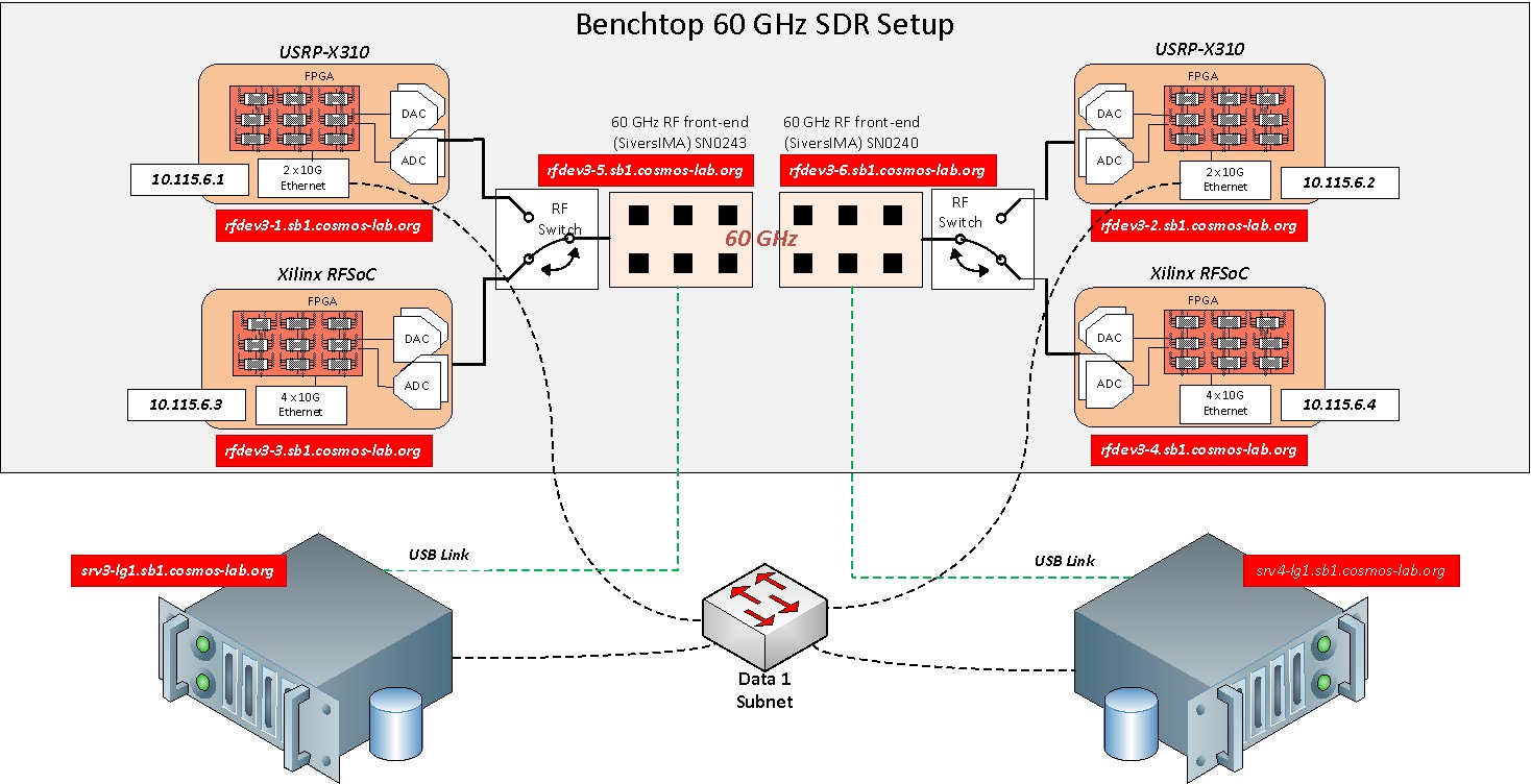
Experiment Setup
COSMOS SB1 Nodes
Follow the steps below to gain access to COSMOS sb1 and set up nodes with appropriate image:
- If you don't have a COSMOS account already, you need to sign up.
- Create a resource reservation on sb1.
- Login into sb1
console.sb1.cosmos-lab.orgusing SSH.not_a_user@laptop:~$ ssh -Y your_username@console.sb1.cosmos-lab.org - Make sure all the nodes and devices of this reservation are turned off:
your_username@console:~$ omf tell -a offh -t system:topo:allres - Load the
rfsoc_sivers_sb1.ndzonsrv1-in1andsrv1-in2.your_username@console:~$ omf load -i rfsoc_sivers_sb1.ndz -t srv1-in1,srv1-in2 - Power on all the required resources.
your_username@console:~$ omf tell -a on -t srv1-in1,srv1-in2,rfdev3-in1,rfdev3-in2,sdr2-in1,sdr2-in2 - Check the status of the nodes and devices of sb1.
your_username@console:~$ omf stat -t system:topo:allres - Configure the RF switches to connect RFSoC with Sivers array
your_username@console:~$ curl "am1.cosmos-lab.org:5054/rf_switch/set?name=rfsw1.sb1.cosmos-lab.org,rfsw2.sb1.cosmos-lab.org&switch=1,2,3,4&port=2"
- Make sure the RF switches are configured correctly (all switches set to port 2)
your_username@console:~# curl am1.cosmos-lab.org:5054/rf_switch/status?name=rfsw1.sb1.cosmos-lab.org,rfsw2.sb1.cosmos-lab.org

<response status="OK">
  <rf_switch name="rfsw1.sb1.cosmos-lab.org" num_of_switches="4">
    <switch number="1" port="2"/>
    <switch number="2" port="2"/>
    <switch number="3" port="2"/>
    <switch number="4" port="2"/>
  </rf_switch>
  <rf_switch name="rfsw2.sb1.cosmos-lab.org" num_of_switches="4">
    <switch number="1" port="2"/>
    <switch number="2" port="2"/>
    <switch number="3" port="2"/>
    <switch number="4" port="2"/>
  </rf_switch>
</response>
RFSoC Setup
Every time we power cycle the FPGAs, we need to download the firmware (i.e., linux image, rootfs, bistream) using the Xilinx XSCT tool over JTAG. Please note the this process will take around 5-10'.
your_username@console:~$ ssh -Y root@srv1-in1
root@srv1-in1:~$ cd mmwsdr/fpga/nonrt-ch1/jtag/sb1_sdr2_in1/
root@srv1-in1:~/mmwsdr/fpga/nonrt-ch1/jtag/sb1_sdr2_in1$ xsct download_firmware.tcl
your_username@console:~$ ssh -Y root@srv1-in2
root@srv1-in2:~$ cd mmwsdr/fpga/nonrt-ch1/jtag/sb1_sdr2_in2/
root@srv1-in2:~/mmwsdr/fpga/nonrt-ch1/jtag/sb1_sdr2_in2$ xsct download_firmware.tcl
Network Interface Setup
Using the information available in COSMOS WiKi we need to configure the ethernet interfaces.
| First corner (1-1) | |||
|---|---|---|---|
| Device | Control Network | Data Network 1 | Data Network 2 |
| Support Server | 10.37.1.3 (srv1-in1) | 10.38.1.3 (srv1a-in1) | 10.39.1.3 (srv1b-in1) |
| RFSoC Device | 10.37.6.3 (sdr2-in1) | 10.38.6.3 (sdr2-in1a) | 10.39.6.3 (sdr2-in1b) |
root@srv1-in1:~# ip link set enp1s0 mtu 9000 up
root@srv1-in1:~# ip link set enp3s0 mtu 9000 up
root@srv1-in1:~# ip addr add 10.38.1.3/16 dev enp1s0
root@srv1-in1:~# ip addr add 10.39.1.3/16 dev enp3s0
| Second corner (20-20) | |||
|---|---|---|---|
| Device | Control Network | Data Network 1 | Data Network 2 |
| Support Server | 10.37.1.4 (srv1-in2) | 10.38.1.4 (srv1a-in2) | 10.39.1.4 (srv1b-in2) |
| RFSoC Device | 10.37.6.4 (sdr2-in2) | 10.38.6.4 (sdr2-in2a) | 10.39.6.4 (sdr2-in2b) |
root@srv1-in2:~# ip link set enp1s0 mtu 9000 up
root@srv1-in2:~# ip link set enp3s0 mtu 9000 up
root@srv1-in2:~# ip addr add 10.38.1.4/16 dev enp1s0
root@srv1-in2:~# ip addr add 10.39.1.4/16 dev enp3s0
Environment Setup
To control the Sivers using a local connection we need to setup the FTDI drivers for every new ssh connection.
root@srv1-in1:~$ source ~/mmwsdr/host/scripts/sivers_ftdi.sh
Software Update
Update the software:
root@srv1-in1:~$ cd mmwsdr
root@srv1-in1:~/mmwsdr$ git pull
root@srv1-in2:~$ cd mmwsdr
root@srv1-in2:~/mmwsdr$ git pull
Demos
In the following subsections, you can find detailed descriptions for each demo.
Basic
- video.py In this script we show the control of the SDR movement. Each SDR is mounted on top of an XY-Table that allows for independent movement in the horizontal plane and rotation along the vertical axis. To control the XY-Table we use the HTTP API detailed in the following page. To visualize this motion we open a live stream from a camera using OpenCV.
root@srv1-in1:~/mmwsdr/host/demos/basic$ python video.py --node srv1-in1 - onenode.py: In this demo we control a single SDR node. We create an SDR object and an XY-Table object using the
mmwsdrlibrary. The SDR object configures and controls a Xilinx RFSoC ZCU111 eval board and a Sivers IMA transceiver board. A user can provide arguments to the script, such as the carrier frequency, the COSMOS node id and the transceiver mode. The script by default starts a local connection with a carrier frequency at 60.48 GHz in receive mode.- Start the transmitter in
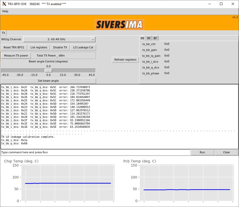
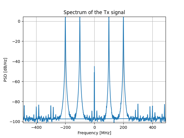
srv1-in1:root@srv1-in1:~/mmwsdr/host/demos/basic$ python onenode.py --freq 60.48e9 --node srv1-in1 --mode tx
- Start the receive in
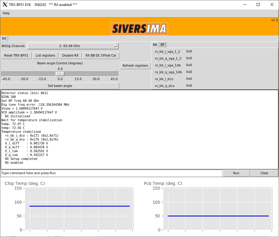
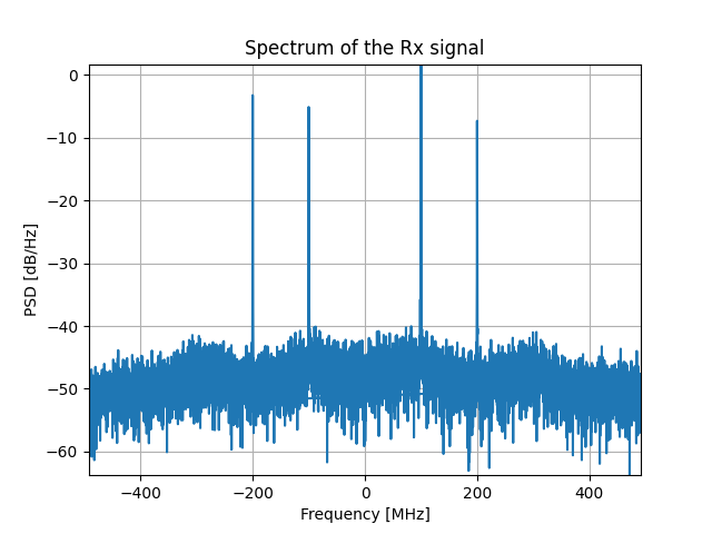
srv1-in2:root@srv1-in2:~/mmwsdr/host/demos/basic$ python onenode.py --freq 60.48e9 --node srv1-in2 --mode rx
- Observe the received signal in frequency-domain:
- Start the transmitter in
- ederarray.py:
The Python drivers of the Sivers library require Python 2. One way to remove this dependence is to remotely control the Sivers array with an HTTP server. The script 'ederarray.py' instantiates an object to control the Sivers array and starts the HTTP server to listen to control commands
root@srv1-in1:~/mmwsdr/host/mmwsdr/array$ python ederarray.py -u SN0240root@srv1-in2:~/mmwsdr/host/mmwsdr/array$ python ederarray.py -u SN0243
- twonode.py: In this demo we control both the SDR nodes using a single script. We create an SDR object and an XY-Table object for each node using the
mmwsdrlibrary. The SDR object configures and controls a Xilinx RFSoC ZCU111 eval board and a Sivers IMA transceiver board. Shown below are the commands to start an HTTP server on srv1-in1 and to run twonode.py script on srv1-in2. twonode.py script in this case connects directly to its local Sivers front-end SN0240 and it connects to SN0243 via the HTTP server running on srv1-in2.- Start the remote Eder server on srv1-in1 :
root@srv1-in1:~/mmwsdr/host/mmwsdr/array$ python ederarray.py -u SN0240 - Start the experiment on the local server srv1-in2:
root@srv1-in2:~/mmwsdr/host/demos/basic$ python twonode.py --freq 60.48e9 --mode tx --node srv1-in2
- Start the remote Eder server on srv1-in1 :
Channel Sounder
In this demo, we show a frequency-domain channel sounder at 60 GHz. We generate N_FFT symbols in frequency domain. We generate a wide-band sequence filling [sc_min, sc_max] sub-carries with random 4-QAM symbols. We use IFFT to get the time-domain TX sequence. We transmit the data from SDR1 with cyclic repeat. We receive 100 frames of N_FFT data from SDR2. The user can select to save or process the data. When we process the data
In this section we demonstrated a frequency-domain channel sounder. We generate a tx sequence using mmwave.utils.waveform.wideband function.
Calibration
In this demo, we use the calibration techniques by Sivers. The performance of the calibration can be further improved with the IQ calibration techniques described in the following papers,
- A. Dhananjay, K. Zheng, M. Mezzavilla, L. Iotti, D. Shasha, and S. Rangan, "Pi-Radio v1: Calibration techniques to enable fully-digital beamforming at 60 GHz," Computer Networks, Volume 196, 2021, 108220, ISSN 1389-1286, https://doi.org/10.1016/j.comnet.2021.108220.
- A. Dhananjay, K. Zheng, J. Haarla, L. Iotti, M. Mezzavilla, D. Shasha, and S. Rangan, "Calibrating a 4-channel Fully-Digital 60 GHz SDR," In Proc. of the 14th International Workshop on Wireless Network Testbeds, Experimental evaluation & Characterization (WiNTECH'20). Association for Computing Machinery, New York, NY, USA, 40–47. https://doi.org/10.1145/3411276.3412195
Originally this techniques target a 4-channel fully-digital array. However, the algorithms are versatile and can target the phased arrays as well.
Calibrate RX IQ imbalance
root@srv1-in1:~/mmwsdr/host/mmwsdr/array$ python ederarray.py --unit SN0240
Calibrate TX IQ imbalance
root@srv1-in1:~/mmwsdr/host/mmwsdr/array$ python ederarray.py --unit SN0240
Array Pattern
root@srv1-in1:~/mmwsdr/host/mmwsdr/array$ python ederarray.py --unit SN0240
root@srv1-in2:~/mmwsdr/host/demos/basic$ python twonode.py --freq 60.48e9 --mode tx
Beam Tracking
Attachments (5)
- Sivers_TX_SN0240.jpg (162.6 KB ) - added by 6 years ago.
- Sivers_RX_SN0243.jpg (128.2 KB ) - added by 6 years ago.
- rfsoc_tx.png (43.1 KB ) - added by 6 years ago.
- rfsoc_rx.png (32.7 KB ) - added by 6 years ago.
- MISO_tutorial.jpg (256.2 KB ) - added by 6 years ago.
Download all attachments as: .zip