Site Navigation
Getting Started with InterDigital 5G NR Performance System
Table of Contents
Description
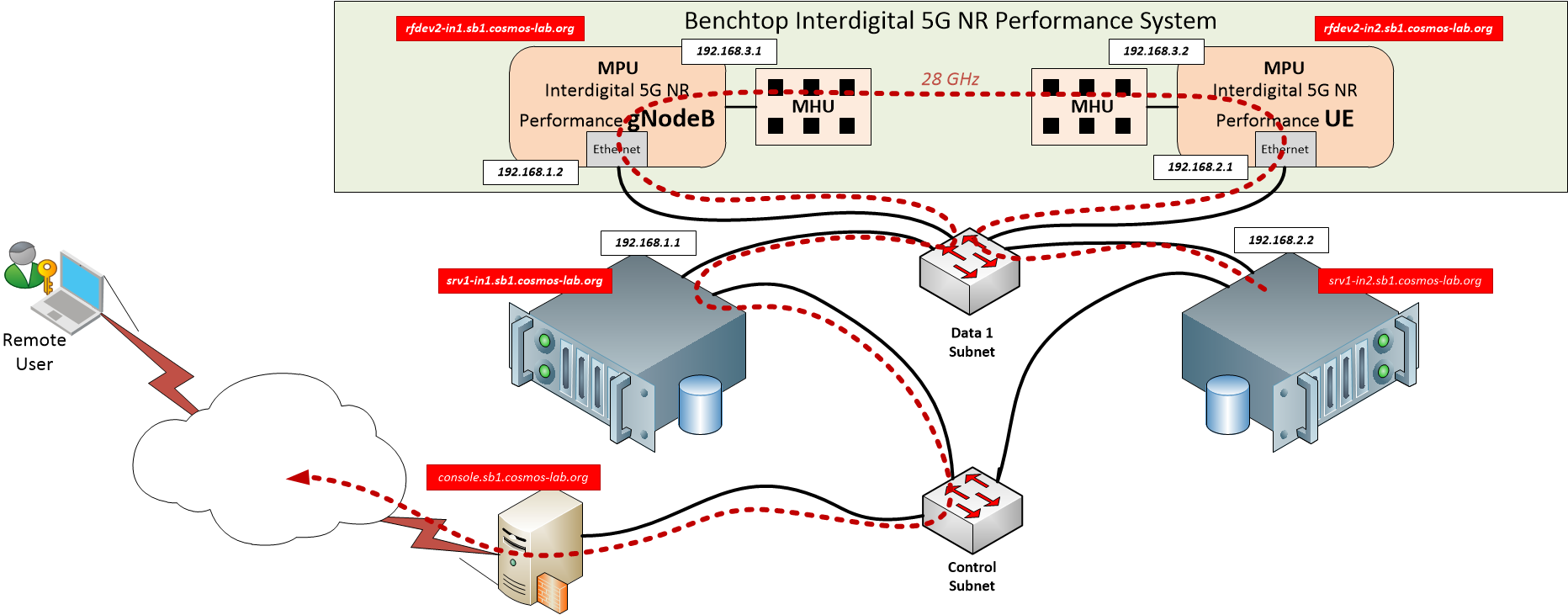
In this tutorial we'll demonstrate how to use InterDigital 5G-NR Performance platform. The setup for the experiment is shown in Figure 1.
As can be seen from the figure, the setup consists of one gNodeB and one UE unit and the two sandbox 1 servers (in this case srv1-in1.sb1.cosmos-lab.org and srv1-in2.sb1.cosmos-lab.org). The first server (srv1-in1) acts as a gateway while the second one is acting as a UE computing platform (to which a UE modem is attached). The 5G Platform devices and the nodes are connected to the sandbox 1 data 1 network and rely on IP routing to ensure that the traffic flow from the client follows the dashed red line in the figure. The intended route is divided into three segments (IP subnets):
- gNodeB Subnet (192.168.1.X) - connecting gateway to the gNodeB device
- UE Subnet (192.168.2.X) - connects client node to the UE device
- 5G Subnet (192.168.3.X) - connects UE to the gNodeB over the 5G link
This setup requires configuring the routing tables on all 4 devices to ensure appropriate traffic flow (in addition to a common Data 1 Ethernet that is shared between all 4 units, the server nodes also have a second direct Ethernet connection through the Control network that is used for node management and metric collection).
Prerequisites
In order to access the test bed, create a reservation and have it approved by the reservation service. Access to the resources is granted only after the reservation is confirmed. Please follow the process shown on the COSMOS work flow page to get started.
Tutorial Setup
Follow the steps below to gain access to the sandbox 1 console and set up nodes with appropriate images.
- If you don't have one already, sign up for a COSMOS account
- Create a resource reservation on sandbox 1
- Prepare your computer (i.e. laptop) for 5G-NR status page access: either prepare ssh tunnel thought the sandbox 1 console to gNodeB server node, port 3005 (i.e. map localhost:3005 to srv1-in1.sb1.cosmos-lab.org:3005) or follow the instructions to establish a VPN tunnel to the COSMOS sandbox 1. This will be used by the browser to connect to a web server running on the server nodes.
- Login into sandbox 1 console (console.sb1.cosmos-lab.org) with two SSH sessions. The first session will be used for access to gNodeB while the second will be dedicated to handling UE.
- Make sure all the nodes and devices used in the experiment are turned off:
omf tell -a offh -t srv1-in1,srv1-in2,rfdev2-in1,rfdev2-in2
- Load the images on the computing nodes: in each of the two session, start the omf image loading commands:
| SSH session 1 for gNodeB | SSH Session 2 for UE |
omf load -t srv1-in1 -i ID-5G-gNB-rc.ndz -r 50 | omf load -t srv1-in2 -i ID-5G-UE.ndz -r 50
|
- Turn the server nodes and NR platform devices on:
omf tell -a on -t srv1-in1,srv1-in2,rfdev2-in1,rfdev2-in2
Experiment Execution
Configure Routing on the two compute nodes
- Execute NR gNB setup script on srv1-in1
userid@console:~$ ssh root@srv1-in1
root@srv1-in1:~$ ./setup_gNodeB.sh
---------------
Make sure to start the gNodeB modem on the MPU by logging in with:
sshpass -p root ssh -o StrictHostKeyChecking=no root@192.168.1.2
and running:
root@NR-SW-MPU-gNB:~# ./start_all.sh
----------------
net.ipv4.ip_no_pmtu_disc = 1
root@srv1-in1:~#
- Execute NR UE setup script on srv1-in2.
userid@console:~$ ssh root@srv1-in2
root@srv1-in2:~$ ./setup_UE.sh
The two scripts setup routing to push the test traffic from the server that is attached to UE through the 5G-NR link.
Routing Scripts
The two scripts are shown in the table below:
setup_gNodeB.sh |
#!/bin/bash echo "---------------" echo "Make sure to start the gNodeB modem on the MPU by logging in with:" echo "sshpass -p "root" ssh -o StrictHostKeyChecking=no root@192.168.1.2" echo "and running:" echo "root@NR-SW-MPU-gNB:~# ./start_all.sh" echo "----------------" # Turn on routing echo 1 > /proc/sys/net/ipv4/ip_forward sysctl -w net.ipv4.ip_no_pmtu_disc=1 # Add rotuing for the two subnets "behind" the gNodeB ip route add 192.168.2.0/24 via 192.168.1.2 ip route add 192.168.3.0/24 via 192.168.1.2 # as well as for the measurements to come back from the UE over the wire ip route add 192.168.2.1 via 10.37.1.4 dev eth1 # and configure NAT for them iptables -t nat -A POSTROUTING -o eth1 -j MASQUERADE iptables -A FORWARD -i eth1 -o eth0 -m state --state RELATED,ESTABLISHED -j ACCEPT iptables -A FORWARD -i eth0 -o eth1 -j ACCEPT |
setup_UE.sh |
#!/bin/bash echo "---------------" echo "Make sure to start the UE modem on the MPU by logging in with:" echo "sshpass -p "root" ssh -o StrictHostKeyChecking=no root@192.168.2.1" echo "and running:" echo "root@NR-SW-MPU-UE:~# ./start_all.sh" echo "----------------" # Turn on routing echo 1 > /proc/sys/net/ipv4/ip_forward sysctl -w net.ipv4.ip_no_pmtu_disc=1 # Route all internal 5G traffic through the UE MPU ip route add 192.168.3.0/24 via 192.168.2.1 dev eth0 ip route add 192.168.1.0/24 via 192.168.2.1 dev eth0 # Testbed bound traffic stil goes over the control subnet ip r add 10/8 dev eth1 # Everything else goes over the 5G link # (remove default over control network) ip r del default dev eth1 ip r add default via 192.168.2.1 dev eth0 |
Start services on the two MPUs
- ssh into gNodeB MPU at 192.168.1.2 with username "root" and password "root" and execute the setup script "start_all.sh":
root@srv1-in1:~# sshpass -p "root" ssh -o StrictHostKeyChecking=no root@192.168.1.2
root@NR-SW-MPU-gNB:~# ./start_all.sh
root@NR-SW-MPU-gNB:~# metal: info:      metal_uio_dev_open: No IRQ for device 3ed80000.shm.

root@NR-SW-MPU-gNB:~# exit
logout
Connection to 192.168.1.2 closed.
root@srv1-in1:~#
- ssh into UE MPU at 192.168.2.1 with username "root" and password "root: and execute the setup script "start_all.sh":
root@srv1-in2:~# sshpass -p "root" ssh -o StrictHostKeyChecking=no root@192.168.2.1
root@NR-SW-MPU-UE:~# ./start_all.sh
root@NR-SW-MPU-UE:~# metal: info:      metal_uio_dev_open: No IRQ for device 3ed80000.shm.

root@NR-SW-MPU-UE:~# exit
logout
Connection to 192.168.2.1 closed.
root@srv1-in2:~#
The two scripts will start the appropriate firmware on both NR Platform devices and the script "stop_all.sh" can be used to terminate execution. The NR Platform will automatically “connect” a link between the gNB and UE. This can be verified via the NR GUI.
Check the Routing
Use mtr utility to confirm that traffic is going through the NR link:
root@srv1-in2:~# mtr -c 1 -r 8.8.8.8
Start: Fri Sep 22 13:14:06 2023
HOST: srv1-in2.sb1.cosmos-lab.org Loss%   Snt   Last   Avg  Best  Wrst StDev
  1.|-- 192.168.2.1                0.0%     1    0.2   0.2   0.2   0.2   0.0
  2.|-- 192.168.3.1                0.0%     1    1.1   1.1   1.1   1.1   0.0
  3.|-- 192.168.1.1                0.0%     1    1.2   1.2   1.2   1.2   0.0
  4.|-- ???                       100.0     1    0.0   0.0   0.0   0.0   0.0
  5.|-- ???                       100.0     1    0.0   0.0   0.0   0.0   0.0
  6.|-- vlan-102-ar01-winlab-fsci  0.0%     1    1.9   1.9   1.9   1.9   0.0
  7.|-- 172.29.50.14               0.0%     1    2.1   2.1   2.1   2.1   0.0
  8.|-- 172.29.6.25                0.0%     1    1.8   1.8   1.8   1.8   0.0
  9.|-- 172.29.6.58                0.0%     1    3.2   3.2   3.2   3.2   0.0
 10.|-- 172.29.6.96                0.0%     1    2.7   2.7   2.7   2.7   0.0
 11.|-- ???                       100.0     1    0.0   0.0   0.0   0.0   0.0
 12.|-- 142.251.249.125            0.0%     1    3.6   3.6   3.6   3.6   0.0
 13.|-- 216.239.40.167             0.0%     1    2.7   2.7   2.7   2.7   0.0
 14.|-- dns.google                 0.0%     1    2.8   2.8   2.8   2.8   0.0
root@srv1-in2:~#
GUI Setup & Instructions
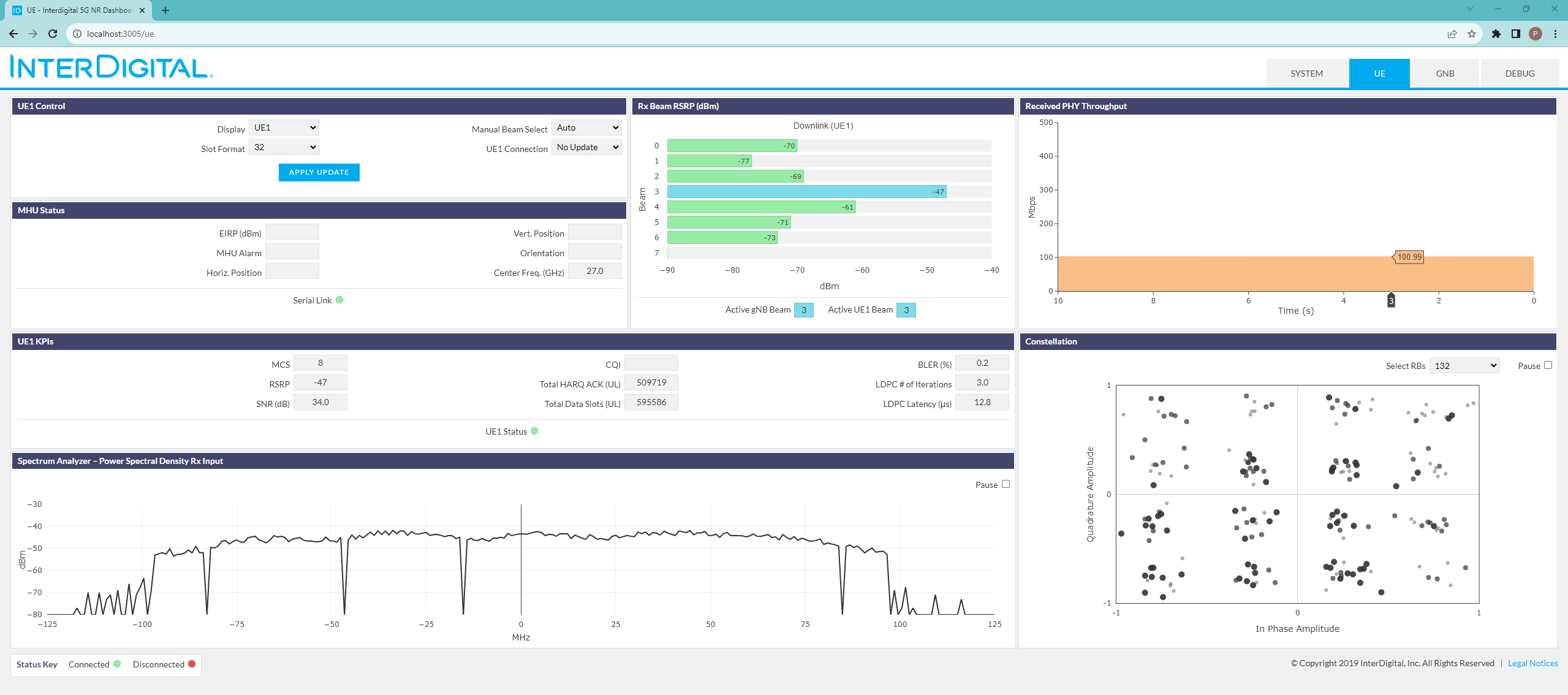
Note that the GUI web server has already been started during Linux startup. Open the browser and point it at http://localhost:3005 (if using ssh tunneling) or at http://srv1-in1.sb1.cosmos-lab.org:3005 if using VPN; login credentials for the GUI are: admin/admin.
Once the page comes up, navigate to the DEBUG tab of the GUI:
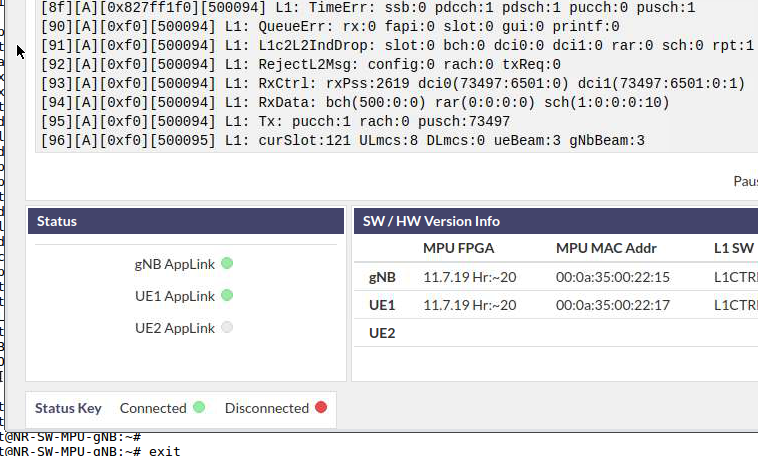
and click on the gNB Applink and UE1 Applink circles (LEDs) located under the Status bar:
When selected, the LED will turn “green” indicating the GUI is communicating with the respective node.
Enable Logging to DataBase
The configuration file WEBSERVER/server/config.js located on srv1-in1.sb1.cosmos-lab.org can be modified to enable logging to the database as follows:
config.js |
//MongoDB Database parameters dbAvailable: true, dbStore: true, dbCollectionName: "nr_guidata", //This is not a fixed value and can be changed dbHost: "127.0.0.1", //Address of databases server dbPort: 27017, //End Database parameters |
Once the configuration file has been saved the server will automatically restart and all data streamed to the GUI will be saved in the database. The Mongo client can be used to browse or extract data. The data model in use can be found in the following file: WEBSERVER/server/backend/models/tlvDataItem.js
Sending iperf data between the gNB and UE
The following commands are provided as an example of how to send Downlink iperf data traffic on the NR 28GHz mmW OTA link via the compute machines that are attached to the gNB and UE platforms
- In the UE console session start the iperf server
iperf3 -s -i 1 - In the gNodeB session strat the iperf client
iperf3 -c 192.168.2.2 -i 1 -u -b 20M -l 1472 -t 30
The results should be (the actual link performance will also depend on the physical antenna alignment):
gNodeB (srv1-in1) | UE (srv1-in2) |
root@srv1-in1:~# iperf3 -c 192.168.2.2 -i 1 -u -b 20M -l 1472 -t 3 Connecting to host 192.168.2.2, port 5201 [ 4] local 192.168.1.1 port 41249 connected to 192.168.2.2 port 5201 [ ID] Interval Transfer Bandwidth Total Datagrams [ 4] 0.00-1.00 sec 2.15 MBytes 18.0 Mbits/sec 1532 [ 4] 1.00-2.00 sec 2.38 MBytes 20.0 Mbits/sec 1698 [ 4] 2.00-3.00 sec 2.39 MBytes 20.0 Mbits/sec 1699 - - - - - - - - - - - - - - - - - - - - - - - - - [ ID] Interval Transfer Bandwidth Jitter Lost/Total Datagrams [ 4] 0.00-3.00 sec 6.92 MBytes 19.3 Mbits/sec 0.141 ms 69/4929 (1.4%) [ 4] Sent 4929 datagrams iperf Done. root@srv1-in1:~# | root@srv1-in2:~# iperf3 -s -i 1 ----------------------------------------------------------- Server listening on 5201 ----------------------------------------------------------- Accepted connection from 192.168.1.1, port 55250 [ 5] local 192.168.2.2 port 5201 connected to 192.168.1.1 port 41249 [ ID] Interval Transfer Bandwidth Jitter Lost/Total Datagrams [ 5] 0.00-1.00 sec 2.12 MBytes 17.7 Mbits/sec 0.130 ms 25/1532 (1.6%) [ 5] 1.00-2.00 sec 2.35 MBytes 19.7 Mbits/sec 0.142 ms 25/1698 (1.5%) [ 5] 2.00-3.00 sec 2.36 MBytes 19.8 Mbits/sec 0.141 ms 19/1699 (1.1%) [ 5] 3.00-3.04 sec 0.00 Bytes 0.00 bits/sec 0.141 ms 0/0 (-nan%) - - - - - - - - - - - - - - - - - - - - - - - - - [ ID] Interval Transfer Bandwidth Jitter Lost/Total Datagrams [ 5] 0.00-3.04 sec 6.92 MBytes 19.1 Mbits/sec 0.141 ms 69/4929 (1.4%) ----------------------------------------------------------- Server listening on 5201 ----------------------------------------------------------- |
Analyze the NR link performance via the NR GUI
Navigate to the DEBUG tab of the GUI and select the gNB Applink and UE1 Applink buttons located under the Status bar. When selected the LED will turn “green” indicating the GUI is communicating with the respective node.
Shutting Down Resources
Turn off the server nodes and NR platform devices:
omf tell -a offh -t srv1-in1,srv1-in2,rfdev2-in1,rfdev2-in2
Saving the Node Images
If you modify software on any of the server nodes save the image by the [omf save image commands] but don't forget to first prepare the node by executing (this is the example for srv3-lg1 node):
root@srv1-in1:~# ./prepare.sh
This script will “clean” and “dump” old log files and any other unnecessary files that do not need to be saved as part of the image, thereby reducing the size of the saved image. At the end of this script, the node will shutdown (it might block your ssh window forcing you to open another one); once back on the console, you can save that node disk image with
username@console:~# omf save -n srv1-in1.sb1.cosmos-lab.org
(please note the -n option and the FQDN for the node both of which are mandatory for successful saving operation).
Attachments (4)
- Select-Debug.png (286.4 KB ) - added by 6 years ago.
- Status-Buttons.png (257.0 KB ) - added by 6 years ago.
-
InterDigital-5G-NR-Tut.png
(160.8 KB
) - added by 2 years ago.
Inter Digital 5G NR routing
-
NR-gui.png
(149.7 KB
) - added by 2 years ago.
NR GUI
Download all attachments as: .zip


